


14 - 32
Chapter 14 Common Functions
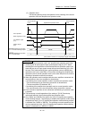
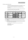
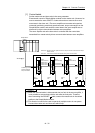
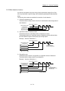
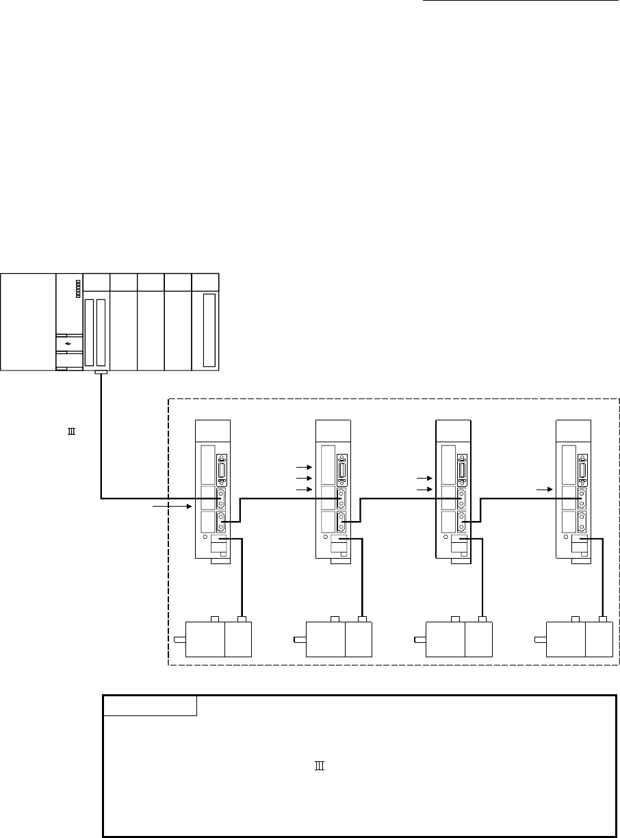
[1] Control details
Set the master axis and slave axis in the servo parameter.
Execute each control of Simple Motion module for the master axis. (However, be
sure to execute the servo ON/OFF of slave axis and error reset at servo error
occurrence in the slave axis.) The servo amplifier set as master axis receives
command (positioning command, speed command, torque command) from the
Simple Motion module, and send the control data to the servo amplifier set as
slave axis by driver communication between servo amplifiers.
The servo amplifier set as the slave axis is controlled with the control data
transmitted from master axis by driver communication between servo amplifiers.
Simple Motion
module
d2d1
Axis 1
ABS/INC
Axis 2
INC
d3 d4
Axis 3
INC
Axis 4
INC
Positioning command/
speed command/
torque command
[Driver
communication]
Control data 1
Control data 2
Control data 3
[Driver
communication]
Control data 2
Control data 3
[Driver
communication]
Control data 3
Master axis
Slave axis 1 Slave axis 2 Slave axis 3
Master axis: Position command, speed command or torque command is received from Simple
Motion module.
Slave axis : Control data is received from Master axis by driver communication.
SSCNET (/H)
POINT
(1) When the communication is disconnected due to a fault in the servo amplifier, it
is not possible to communicate with the axis after the faulty axis. Therefore,
when connecting the SSCNET
cable, connect the master axis in the closest
position to the Simple Motion module.
(2) This function is used for the case to operate by multiple motors in one system.
Connect the master axis and slave axis without slip.