14 - 11
Chapter 14 Common Functions
[4] Program example
The following shows the program example that is used to operate "[Cd.44]
External input signal operation device" of axis 1, axis 4, axis 8, and axis 16
using the limit switch connected to the input module when "2: Buffer memory of
QD77MS" is set in "[Pr.80] External input signal selection".
System configuration
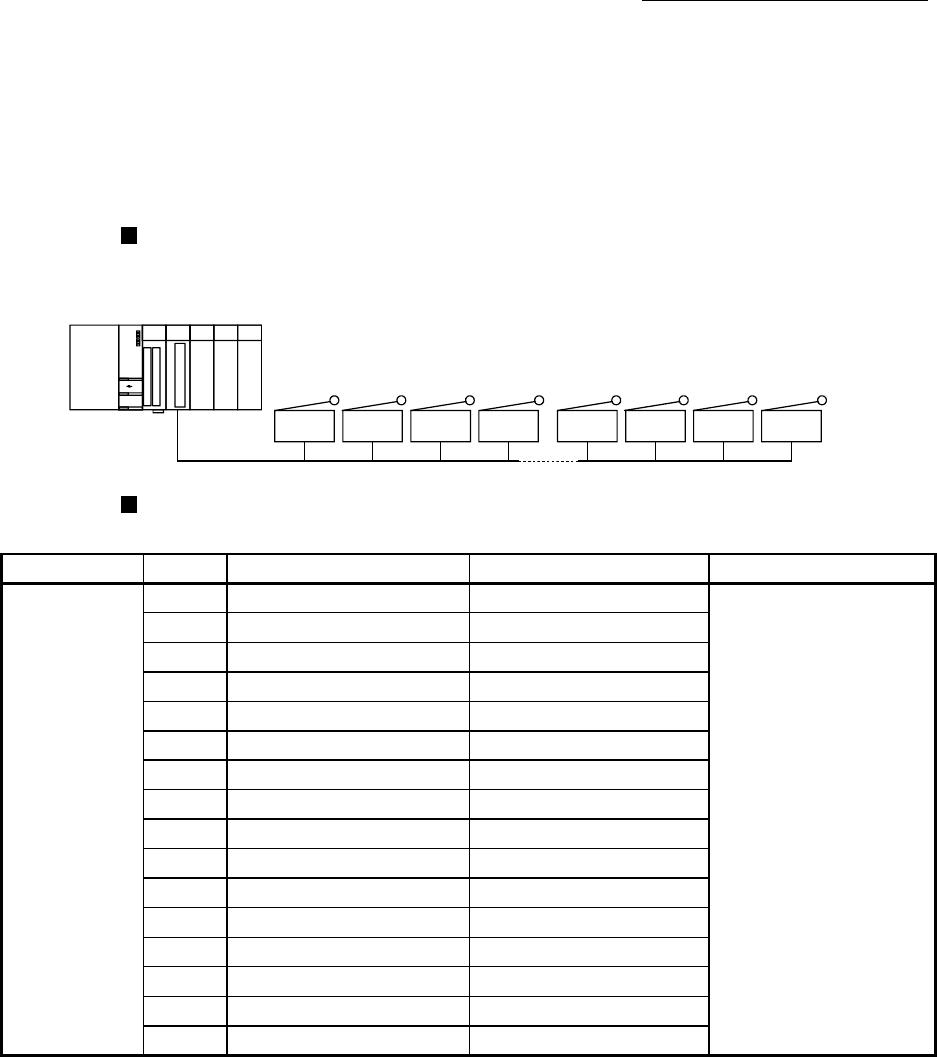
The following shows the system configuration that is used with the program example.
FLS1 RLS1 DOG1 STOP1 FLS4 RLS4 DOG4 STOP4
(1) (2) (3) (4)
X20 to X5F
(1) Q61P
(2) Q10UDEHCPU
(3) QD77MS16 (X0 to X1F/Y0 to Y1F)
(4) QX42 (X20 to X5F)
List of devices to be used
The following shows the device list that is used with the program example.
Device name Device Limit switch to be connected Purpose Description at device ON
External input
(command)
X20 FLS 1 Axis1 FLS ON command
When "[Pr.22] Input
signal logic selection" is
negative logic: ON
When "[Pr.22] Input signal
logic selection" is positive
logic: OFF
X21
RLS 1 Axis1 RLS ON command
X22
DOG 1 Axis1 DOG ON command
X23
STOP 1 Axis1 STOP ON command
X24
FLS 2 Axis4 FLS ON command
X25
RLS 2 Axis4 RLS ON command
X26
DOG 2 Axis4 DOG ON command
X27
STOP 2 Axis4 STOP ON command
X28
FLS 3 Axis8 FLS ON command
X29
RLS 3 Axis8 RLS ON command
X2A
DOG 3 Axis8 DOG ON command
X2B
STOP 3 Axis8 STOP ON command
X2C
FLS 4 Axis16 FLS ON command
X2D
RLS 4 Axis16 RLS ON command
X2E
DOG 4 Axis16 DOG ON command
X2F
STOP 4 Axis16 STOP ON command


