


3 - 29
Chapter 3 Specifications and Functions
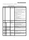
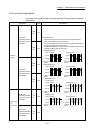
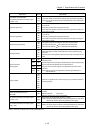
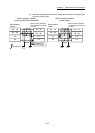
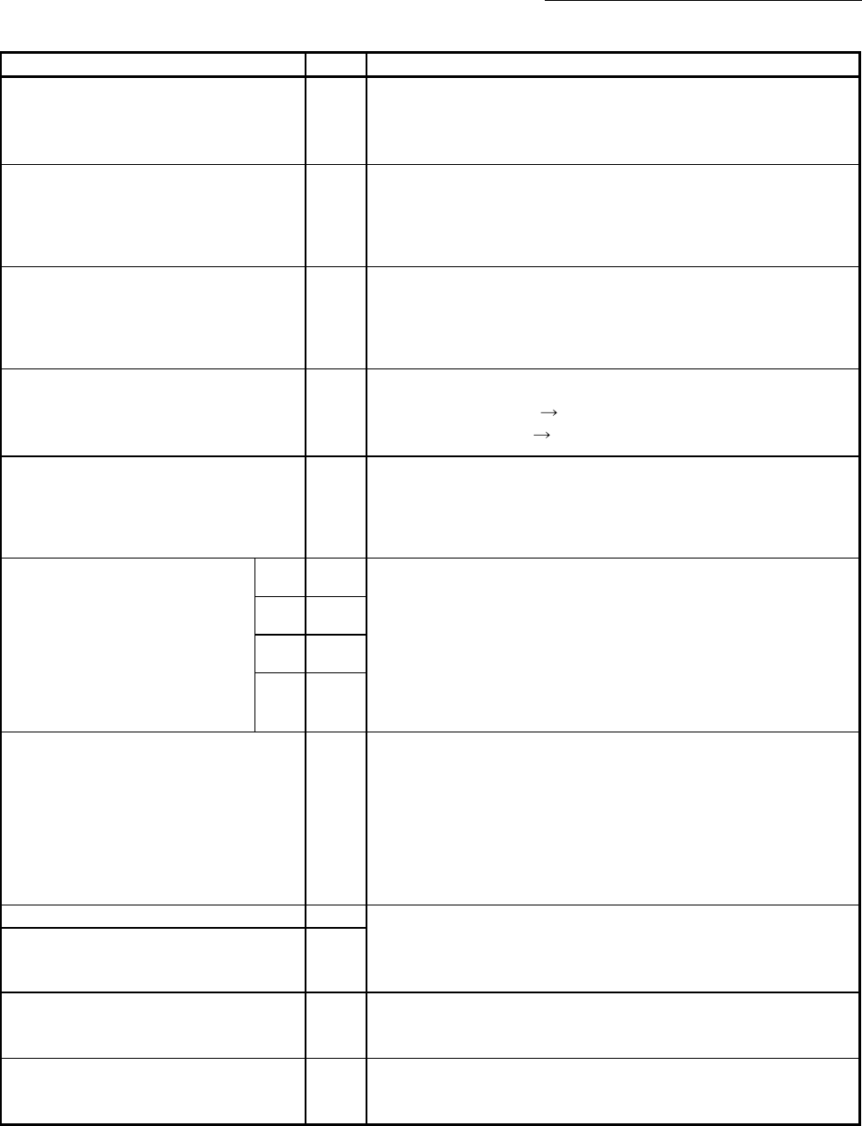
Signal name Pin No. Signal details
Compatibility with the QD75MH
Manual pulse generator power supply output
(+ 5VDC) (5V)
1A20
1A19
• Power supply for manual pulse generator MR-HDP01. (+ 5VDC)
(This power supply is used with the external input signal cable of QD75MH.)
(Note): Do not connect wires other than the signal wires of the manual pulse
generator.
Upper limit signal (FLS)
1A1
1B1
2A1
2B1
• This signal is input from the limit switch installed at the upper limit position
of the stroke.
• Positioning will stop when this signal turns OFF.
• When OPR retry function is valid, this will be the upper limit for finding the
near-point dog signal.
Lower limit signal (RLS)
1A2
1B2
2A2
2B2
• This signal is input from the limit switch installed at the lower limit position
of the stroke.
• Positioning will stop when this signal turns OFF.
• When OPR retry function is valid, this will be the lower limit for finding the
near-point dog signal.
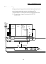
Near-point dog signal (DOG)
1A3
1B3
2A3
2B3
• This signal is used for detecting the near-point dog during OPR.
• The near-point dog OFF ON is detected at the rising edge.
• The near-point dog ON
OFF is detected at the falling edge.
Stop signal (STOP)
1A4
1B4
2A4
2B4
• Input this signal to stop positioning.
• When this signal turns ON, the QD77MS will stop the positioning being
executed.
After that, even if this signal is turned from ON to OFF, the system will not
start.
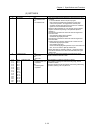
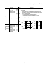
External command/
Switching signal
(DI1) 1A5
• Input a control switching signal during speed-position or position-speed
switching control.
• Use this signal as the input signal of positioning start, speed change request,
skip request and mark detection from an external device.
Set the function to use this signal in "[Pr.42] External command function
selection".
(Note): Set the signal in "[Pr.95] External command signal selection" at
QD77MS16 use.
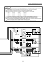
(DI2) 1B5
(DI3) 2A5
(DI4) 2B5
Common (COM)
1A6
1A7
1B6
1B7
2A6
2A7
2B6
2B7
• Common for upper/lower limit, near-point dog, stop, and external command
/switching signals.
Forced stop input signal (EMI) 1A8 • This signal is input when batch forced stop is available for all axes of servo
amplifier.
EMI ON (Opened) : Forced stop
EMI OFF (24VDC input) : Forced stop release
Forced stop input signal common
(EMI.COM)
1B8
Manual pulse generator power supply output
(+ 5VDC) (5V)
1A15
1B15
• Power supply for manual pulse generator. (+ 5VDC)
(Note): This power supply is used for manual pulse generator. It must not be
used except for the manual pulse generator power supply.
Manual pulse generator power supply output
(GND) (SG)
1A14
1B14
• Power supply for manual pulse generator. (GND)
(Note): This power supply is used for manual pulse generator. It must not be
used except for the manual pulse generator power supply.
(Note-1): There are no signals of 2A_ and 2B_ at QD77MS2 use.