


11 - 30
Chapter 11 Manual Control
11.4.4 Creating a program to enable/disable the manual pulse generator operation
A sequence program must be created to execute a manual pulse generator operation.
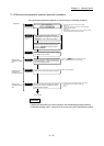
Consider the "required control data setting", "start conditions" and "start time chart"
when creating the program.
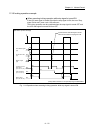
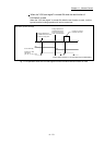
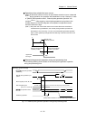
The following shows an example when a manual pulse generator operation is started
for axis 1.
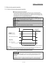
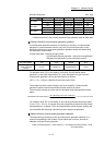
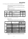
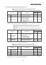
Required control data setting
The control data shown below must be set to execute a manual pulse generator
operation. The setting is carried out with the sequence program.
Setting item
Setting
value
Setting details
Buffer memory address
QD77MS2
QD77MS4
QD77MS16
[Cd.20]
Manual pulse
generator 1 pulse
input magnification
1
Set the manual pulse generator 1 pulse input
magnification.
(1 to 10000 times)
1522+100n
1523+100n
4322+100n
4323+100n
[Cd.21]
Manual pulse
generator enable
flag
1 (0)
Set "1: Enable manual pulse generator
operation". (Set "0: Disable manual pulse
generator operation" when finished with the
manual pulse generator operation.)
1524+100n 4324+100n
n: Axis No.-1
: Refer to Section 5.7 "List of control data" for details on the setting details.
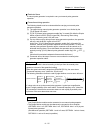
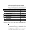
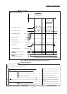
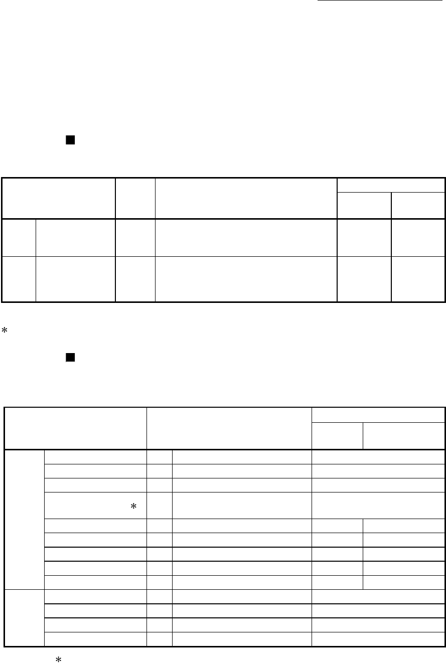
Start conditions
The following conditions must be fulfilled when starting. The required conditions
must also be assembled in the sequence program, and the sequence program
must be configured so the operation will not start if the conditions are not fulfilled.
Signal name Signal state
Device
QD77MS2
QD77MS4
QD77MS16
Interface
signal
PLC READY signal ON PLC CPU preparation completed Y0
READY signal ON QD77MS preparation completed X0
All axis servo ON ON All axis servo ON Y1
Synchronization flag ON
QD77MS buffer memory
The access is possible.
X1
Axis stop signal OFF Axis stop signal is OFF Y4 to Y7 [Cd.180] Axis stop
Start complete signal OFF Start complete signal is OFF X10 to X13 [Md.31] Status: b14
BUSY signal OFF QD77MS is not operating XC to XF X10 to X1F
Error detection signal OFF There is no error X8 to XB [Md.31] Status: b13
M code ON signal OFF M code ON signal is OFF X4 to X7 [Md.31] Status: b12
External
signal
Forced stop input signal ON There is no forced stop input –
Stop signal OFF Stop signal is OFF –
Upper limit (FLS) ON Within limit range –
Lower limit (RLS) ON Within limit range –
: If the PLC CPU is set to the asynchronous mode in the synchronization setting, this must be
inserted in the program for interlocking. If it is set to the synchronous mode, it must not be
inserted in the program for interlocking because it is turned ON when the PLC CPU executes
calculation.