


5 - 83
Chapter 5 Data Used for Positioning Control
5.3 List of positioning data
Before explaining the positioning data setting items [Da.1] to [Da.10], [Da.20] to [Da.22]
the configuration of the positioning data will be shown below.
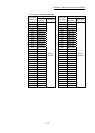
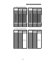
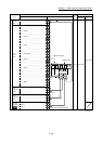
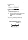
The positioning data stored in the buffer memory of Simple Motion module has the
following type of configuration.
• QD77MS2/QD77MS4
Positioning data No. 600
7990+6000n
7991+6000n
7992+6000n
7994+6000n
7995+6000n
7996+6000n
7997+6000n
7998+6000n
7999+6000n
Positioning data No. 599
7980+6000n
7981+6000n
7982+6000n
7984+6000n
7985+6000n
7986+6000n
7987+6000n
7988+6000n
7989+6000n
Da.1
Da.5
Da.3
Da.4
Buffer memory address
n: Axis No.-1
Up to 600 positioning data items can be set (stored) for each
axis in the buffer memory address shown on the left.
Data is controlled as positioning data No. 1 to 600 for each axis.
One positioning data item is configured of the items shown in
the bold box.
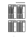
Configuration of positioning identifier
Da.2
Control system
Deceleration time No.
Operation pattern
Acceleration time No.
Buffer memory
Axis to be interpolated
b15 b4 b0b12 b8
2010+6000n
2011+6000n
2012+6000n
2014+6000n
2015+6000n
2016+6000n
2017+6000n
2018+6000n
2019+6000n
Positioning data No. 2
2000+6000n
2001+6000n
2002+6000n
2004+6000n
2005+6000n
2006+6000n
2007+6000n
2008+6000n
2009+6000n
to
Da.1
Da.5
Positioning identifier
Da.7
Arc address
Da.8
Command speed
Da.9
Dwell time/JUMP destination
positioning data No.
Da.10
Da.6
Positioning address/
movement amount
Positioning data No. 1
data No./Number of LOOP
to LEND repetitions
M code/Condition
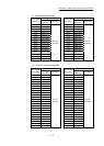
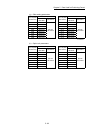
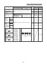
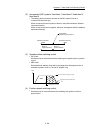
• QD77MS16
Positioning data No. 100
6990+1000n
6991+1000n
6992+1000n
6994+1000n
6995+1000n
6996+1000n
6997+1000n
6998+1000n
6999+1000n
6993+1000n
Positioning data No. 99
6980+1000n
6981+1000n
6982+1000n
6984+1000n
6985+1000n
6986+1000n
6987+1000n
6988+1000n
6989+1000n
6983+1000n
Da.1
Configuration of positioning identifier
Da.2
Control system Operation pattern
Buffer memory
b15 b4 b0b12 b8
Da.3
Da.4 Deceleration time No.
Acceleration time No.
Da.20
Da.21
Da.22
Buffer memory address
n: Axis No.-1
Up to 100 positioning data items can be set (stored) for each
axis in the buffer memory address shown on the left.
No.101 to No.600 are not allocated to buffer memory.
Set with GX Works2.
Data is controlled as positioning data No. 1 to 600 for each axis.
One positioning data item is configured of the items shown in
the bold box.
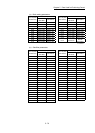
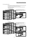
Configuration of axis to be interpolated No.
Buffer memory
b15 b4 b0b12 b8
Axis to be
interpolated No.1
Axis to be interpolated No.2
Axis to be interpolated No.3
6010+1000n
6011+1000n
6012+1000n
6014+1000n
6015+1000n
6016+1000n
6017+1000n
6018+1000n
6019+1000n
6013+1000n
Positioning data No. 2
toDa.1 Da.4
Positioning identifier
Da.9
Dwell time/JUMP destination
positioning data No.
Da.10
6000+1000n
6001+1000n
6002+1000n
6004+1000n
6005+1000n
6006+1000n
6007+1000n
6008+1000n
6009+1000n
6003+1000n
Positioning data No. 1
Da.7
Arc address
Da.8
Command speed
Da.6
Positioning address/
movement amount
to
Da.20
Da.22
Axis to be interpolated
No.
M code/Condition
data No./Number of LOOP
to LEND repetitions