


5 - 22
Chapter 5 Data Used for Positioning Control
5.2 List of parameters
The setting items of the positioning parameter, OPR parameter or servo parameter are
explained in this section.
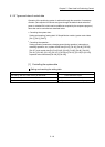
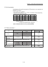
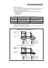
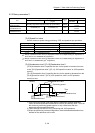
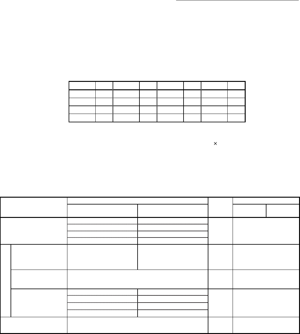
• Guide to buffer memory address
In the buffer memory address, "n" in "1+150n", etc. indicates a value corresponding
to axis No. such as the following table.
Axis No. n Axis No. n Axis No. n Axis No. n
1 0 5 4 9 8 13 12
2 1 6 5 10 9 14 13
3 2 7 6 11 10 15 14
4 3 8 7 12 11 16 15
(Note-1): Calculate as follows for the buffer memory address corresponding to each axis.
(Example) For axis No. 16
1+150n ([Pr.4] Unit magnification (AM))=1+150
15=2251
(Note-2): The range from axis No.1 to 2 (n=0 to 1) is valid in the QD77MS2.
(Note-3): The range from axis No.1 to 4 (n=0 to 3) is valid in the QD77MS4.
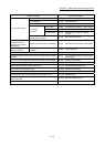
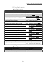
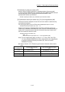
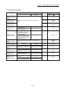
5.2.1 Basic parameters 1
Item
Setting value, setting range
Default
value
Buffer memory address
Value set with GX Works2
Value set with sequence
program
QD77MS2
QD77MS4
QD77MS16
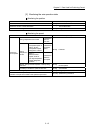
[Pr.1] Unit setting
0 : mm 0
3 0+150n
1 : inch 1
2 : degree 2
3 : PLS 3
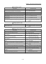
Movement amount per pulse
[Pr.2]
Number of pulses per
rotation (AP)
(Unit : PLS)
1 to 200000000 1 to 200000000 20000
2+150n
3+150n
[Pr.3]
Movement amount per
rotation (AL)
The setting value range differs according to the "[Pr.1] Unit
setting".
20000
4+150n
5+150n
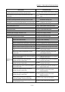
[Pr.4]
Unit magnification (AM)
1 : 1 times 1
1 1+150n
10 : 10 times 10
100 : 100 times 100
1000 : 1000 times 1000
[Pr.7]
Bias speed at start
The setting value range differs according to the "[Pr.1] Unit
setting".
0
6+150n
7+150n
n: Axis No.-1