


16 - 57
Chapter 16 Troubleshooting
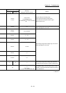
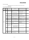
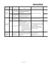
Related buffer memory address
Set range
(Setting with sequence program)
Remedy
QD77MS2
QD77MS4
QD77MS16
Optional data monitor: Data type
setting 1
—
Set the 2-word data to "[Pr.91] Optional data monitor:
Data type setting 1" or "[Pr.93] Optional data monitor:
Data type setting 3" and 0 to "[Pr.92] Optional data
monitor: Data type setting 2" or "[Pr.94] Optional data
monitor: Data type setting 4".
100+150n
Optional data monitor: Data type
setting 2
101+150n
Optional data monitor: Data type
setting 3
102+150n
Optional data monitor: Data type
setting 4
103+150n
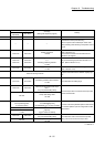
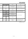
— — — Switch the control mode after turning BUSY OFF.
— — —
Switch the control mode after turning "Zero speed"
([Md.108] Servo status) ON.
1575+100n 4375+100n
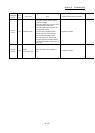
<Control mode setting>
0, 10, 20, 30
Switch the control mode after setting a value within the
range for "[Cd.139] Control mode setting".
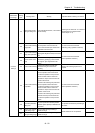
— — —
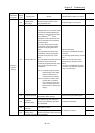
Carry out the control mode switching request after
completing the control mode switching.
— — —
Review so that control mode switching is performed
between the position control mode and continuous
operation to torque control mode or between the speed
control mode and continuous operation to torque
control mode.
30103+200n 28403+100n
<Servo parameter "Absolute
position detection system (PA03)">
0, 1
Match the setting of the servo parameter "Absolute
position detection system (PA03)" to the setting of VCII
series, and turn the PLC READY signal [Y0] from OFF
to ON.
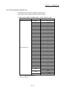
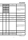
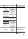
54000+20k
< Mark detection signal setting >
0 to 16
Set a value within the setting range.
54002+20k
< Mark detection data type >
-1 to 12
n: Axis No.-1
k: Mark detection setting No.-1