


5 - 109
Chapter 5 Data Used for Positioning Control
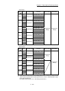
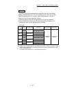
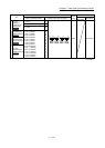
Item
Setting value
Default
value
Buffer memory address
Value set with GX Works2 Value set with sequence program
QD77MS2
QD77MS4
QD77MS16
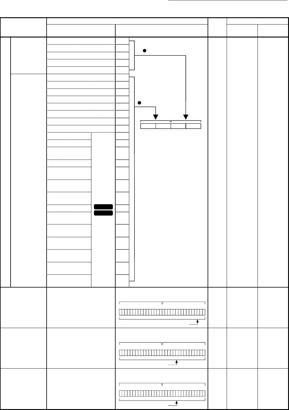
Condition identifier
[Da.15]
Condition
target
01 : Device X 01H
b15 b0b7b8
Condition operator
Condition target
0000H 26100+1000n 22100+400n
02 : Device Y 02H
03 : Buffer memory (1-word) 03H
04 : Buffer memory (2-word) 04H
05 : Positioning data No. 05H
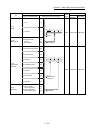
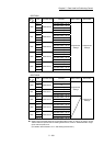
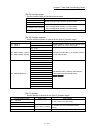
[Da.16]
Condition
operator
01 :
=P1
01H
02 :
P1
02H
03 :
P1
03H
04 :
P1
04H
05 : P1
P2
05H
06 :
P1, P2
06H
07 : DEV=ON 07H
08 : DEV=OFF 08H
10 : Axis 1 selected
QD77MS2
QD77MS4
10H
20 : Axis 2 selected 20H
30 : Axis 1 and 2
selected
30H
40 : Axis 3 selected 40H
50 : Axis 1 and 3
selected
50H
60 : Axis 2 and 3
selected
60H
70 : Axis 1, 2, and
3 selected
70H
80 : Axis 4 selected 80H
90 : Axis 1 and 4
selected
90H
A0 : Axis 2 and 4
selected
A0H
B0 : Axis 1, 2, and
4 selected
B0H
C0 : Axis 3 and 4
selected
C0H
D0 : Axis 1, 3, and
4 selected
D0H
E0 : Axis 2, 3, and
4 selected
E0H
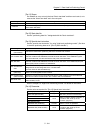
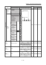
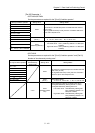
[Da.17]
Address
Buffer memory address
b0b15b16b31
26103 26102
Example)
(High-order) (Low-order)
Buffer memory address
0000H
26102+1000n
26103+1000n
22102+400n
22103+400n
[Da.18]
Parameter 1
Value
b0b15b16b31
26105 26104
Example)
(High-order) (Low-order)
Value
0000H
26104+1000n
26105+1000n
22104+400n
22105+400n
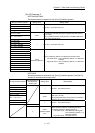
[Da.19]
Parameter 2
Value
b0b15b16b31
26107
26106
Example)
(High-order) (Low-order)
Value
0000H
26106+1000n
26107+1000n
22106+400n
22107+400n
n: Axis No.-1