


16 - 37
Chapter 16 Troubleshooting
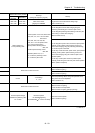
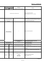
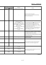
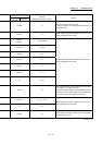
Related buffer memory address
Set range
(Setting with sequence program)
Remedy
QD77MS2
QD77MS4
QD77MS16
— — —
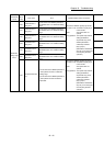
Check the error code in CPU module.
(Refer to the "QCPU User's Manual (Hardware Design,
Maintenance and Inspection)".)
— —
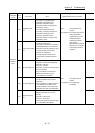
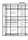
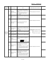
< ZP.PSTRT
start No.>
1 to 600, 7000 to 7004, 9001 to 9004
< ZP.TEACH
teaching data selection>
0: The current feed value is written to the
positioning address.
1: The current feed value is written to the
arc address.
< ZP.TEACH
positioning data No.>
1 to 600
• When executing the ZP.PSTRT
instruction, set the start
No. within the setting range. (Refer to Section 15.3)
• When executing the ZP.TEACH
instruction, set the
teaching data selection and positioning data No. within the
setting range. (Refer to Section 15.4)
• Do not specify the instruction of a non-existent axis by the
ZP.PSTRT
and ZP.TEACH instructions. (Refer to
Section 15.3 to Section 15. 4)
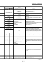
— — —
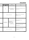
Review the program so that data is not written continuously to
the flash ROM. (Using "[Md.19]" in Section 5.6.1, the number
of flash ROM write times can be monitored.)
(If this error has occurred in a proper using method, writing is
enabled by resetting the error, switching power OFF, then ON,
or resetting the CPU module.)
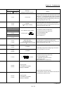
— — — A trouble occurs. Repair.
— — —
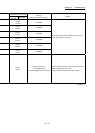
Switch the operation mode after confirming that all input
signals other than synchronization flag [X1] are OFF.
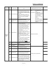
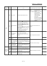
— — —
0+150n 0, 1, 2, 3
With the setting brought into the setting range, turn the PLC
READY signal [Y0] from OFF to ON.
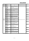
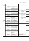
2+150n
3+150n
1 to 200000000
4+150n
5+150n
1 to 200000000
n: Axis No.-1