


5 - 105
Chapter 5 Data Used for Positioning Control
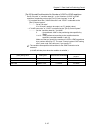
5.5 List of condition data
The illustrations below show the organization of the condition data stored in the buffer
memory of Simple Motion module. The condition data setting items [Da.15] to [Da.19]
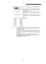
and [Da.23] to [Da.26] are explained in the pages that
follow.
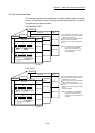
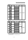
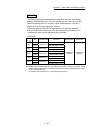
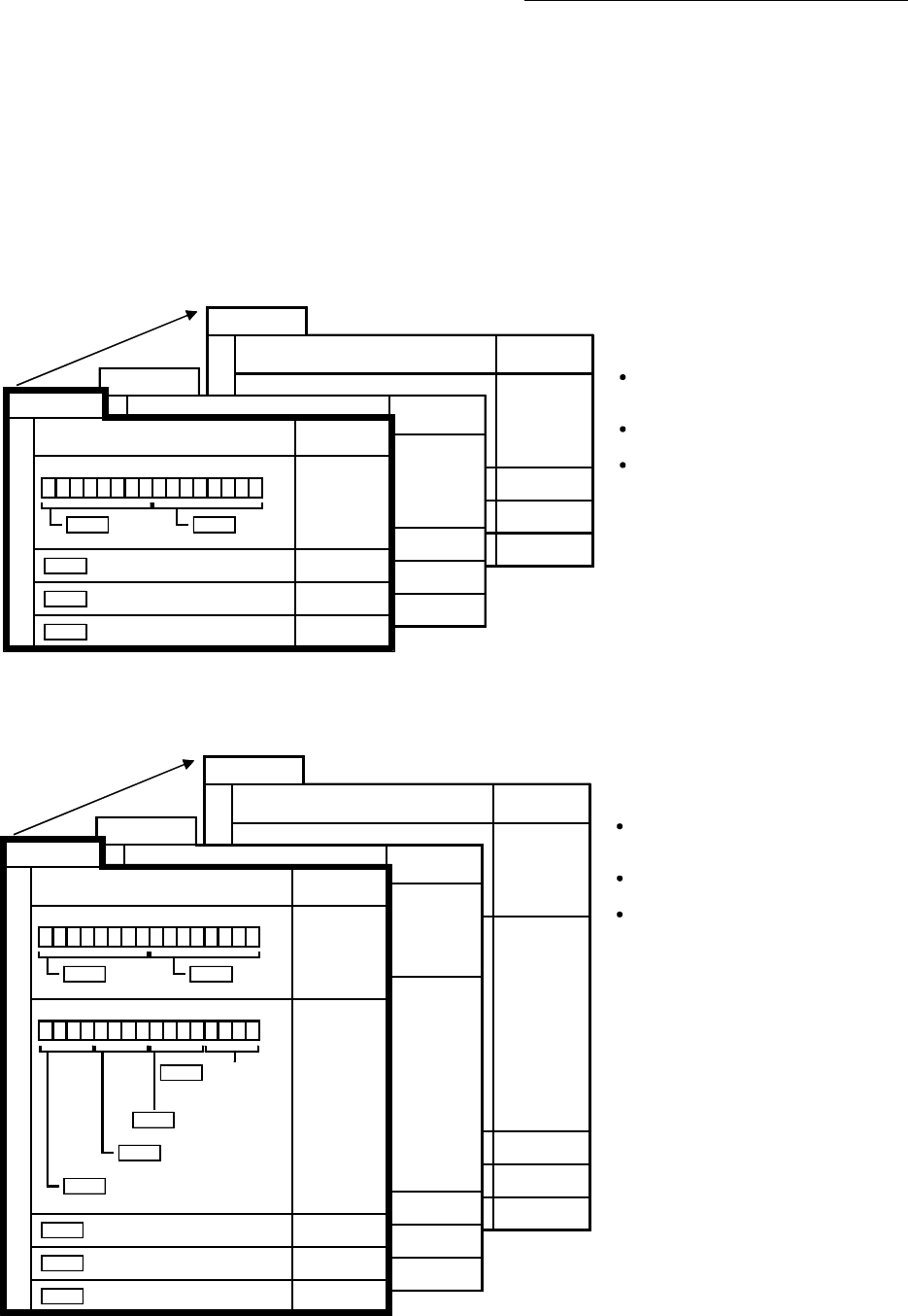
• QD77MS2/QD77MS4
S
t
a
r
t
b
lo
c
k
0
26190+1000n
26192+1000n
26193+1000n
26194+1000n
26195+1000n
26196+1000n
26197+1000n
No.10
Setting item
Buffer memory
address
S
t
a
r
t
b
lo
c
k
0
26110+1000n
26112+1000n
26113+1000n
26114+1000n
26115+1000n
26116+1000n
26117+1000n
No.2
Setting item
Buffer memory
address
26100+1000n
26102+1000n
26103+1000n
26104+1000n
26105+1000n
26106+1000n
26107+1000n
No.1
Setting item
Buffer memory
address
b0b7b8b15
Da.16
Condition
operator
Da.15
Condition
target
Da.17
Address
Da.18
Parameter 1
Da.19
Parameter 2
S
t
a
r
t
b
lo
c
k
0
C
o
n
d
i
t
i
o
n
d
a
t
a
N
o
.
n: Axis No.-1
Up to 10 condition data points can be set
(stored) for each block No. in the buffer
memory addresses shown on the left.
Items in a single unit of condition data are
shown included in a bold frame.
Each axis has five start blocks (block Nos.
0 to 4).
(Note): For information on the organization
of the buffer memory addresses
assigned to the start blocks 1 to 4,
refer to Appendix 1 "List of buffer
memory addresses".
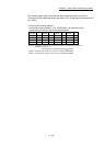
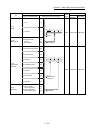
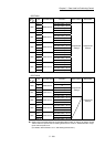
• QD77MS16
22190+400n
22191+400n
22192+400n
22193+400n
22194+400n
22195+400n
22196+400n
22197+400n
No.10
Setting item
Buffer memory
address
22110+400n
22111+400n
22112+400n
22113+400n
22114+400n
22115+400n
22116+400n
22117+400n
No.2
Setting item
Buffer memory
address
n: Axis No.-1
22100+400n
22101+400n
22102+400n
22103+400n
22104+400n
22105+400n
22106+400n
22107+400n
Da.26
Da.23
Da.17 Address
Da.18
Parameter 1
Da.19
Parameter 2
S
t
a
r
t
b
lo
c
k
0
No.1
Setting item
Buffer memory
address
b0b7b8b15
Da.16
Condition
operator
Da.15 Condition
target
b0b7b8b15
Number of simultaneously
starting axes
Da.24
Simultaneously
starting axis
No.1
Da.25
Simultaneously
starting axis No.2
Simultaneously
starting axis No.3
C
o
n
d
i
t
i
o
n
d
a
t
a
N
o
.
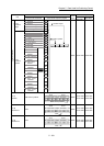
Up to 10 condition data points can be set
(stored) for each block No. in the buffer
memory addresses shown on the left.
Items in a single unit of condition data are
shown included in a bold frame.
Each axis has five start blocks (block Nos.
0 to 4).
Start block 2 to 4 are not allocated to buffer
memory.
Set with GX Works2.
(Note): For information on the organization
of the buffer memory addresses
assigned to the start block 1, refer
to Appendix 1 "List of buffer
memory addresses".