


Reference
Caution
Caution
Note
Section 2-7
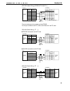
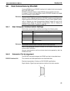
If unit numbers 8 and 9 are set with a C H, a “special I/O unit error” occurs.
When an NT600S is connected to a C H, I/O expansion equipment cannot
be connected. In other words, it will not be possible to connect other special I/O
units, and therefore whatever unit numbers are specified there will be no du-
plication of numbers.
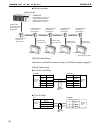
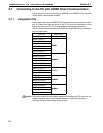
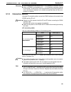
3-7-2 Connection Method
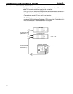
Using the I/O connecting cable, connect the C200H interface unit mounted to the
NT600S and the PC unit.
Always turn off the power at both the PC and PT before connecting the C200H
interface cable.
Otherwise the system may operate unpredictably.
Switch off the power to the NT600S and PC before disconnecting/connecting
the cable.
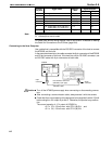
[I/O connecting cable]
Use one of the following models of I/O connecting cable.
Model Cable length (L)
C200H-CN311 30cm
NT20M-CNP711
C200H-CN711
70cm
For connecting C200H/
H
S
/
H
E
/
H
G
/
H
X
NT20M-CNP221
C200H-CN221
2m
H
S
/
H
E
/
H
G
/
H
X
NT20M-CNP521
C200H-CN521
5m
NT20M-CNP131
C200H-CN131
10m
C20H-CN312 30cm
For connecting C H
NT20M-CNP712
C20H-CN712
70cm
F
o
r
c
o
n
n
e
c
t
i
n
g
C
H
NT20M-CNP222
C20H-CN222
2m
In the case of NT20M-CNP models, the connector at the C200H interface
side is a compact one.
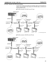
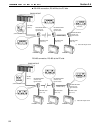
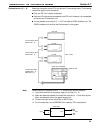
The combined lengths of each of the I/O connecting cables must not exceed a
total of 12 m (or 6 m for C H models).
The cable’s tensile load is 30 N. Do not subject it to loads greater than this.
Otherwise a discontinuity may occur, causing operation to fail.
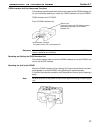
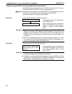
If the I/O connecting cable is passed through a hole, this hole must have a diam-
eter of at least 53 mm . If the top cover is removed the cable can be passed
through a minimum hole size of 33 mm . Replace the cover before mounting
the unit.
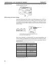
If a C200H-CN or C20H-CN is used as the I/O connection cable,
the connector will project beyond the bottom face of the NT600S.