


Reference
Reference
Section 5-3
6-3 Lamps, Touch Switches, and Numeral Setting
This section describes bit allocation for lamps and touch switches and the method
used to find the numeral input using the numeral setting function, when communi-
cating with the PC using the Host link/NT link/C200H direct.
For details on lamps, touch switches and the numeral setting function, refer to5-6
Lamps (page 135), 5-7 Touch Switches (page 138), and 5-8 Numeral Setting
(page 143).
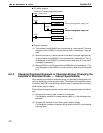
6-3-1 Allocation Bits and Display of Lamps
Lamps are controlled by allocating them to the PC bits. Set the area and bit num-
ber.
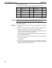
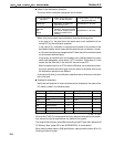
Available allocation bits
The lamps can be allocated to the following PC areas:
Symbol CSeriesPCs Allocated CVM1/CV Series PCs Allocated
DM Data memory
✓
Data memory
✓
CH Internal/Special Relay
✓
Internal/Special Relay
✓
TIM Timer Timer
CNT Counter Counter
HR Holding Relay
✓
--
AR Auxiliary Relay
✓
Auxiliary Relay
LR Link Relay
✓
--
✓
:OK :NG
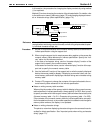
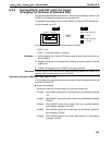
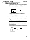
To set the data memory (DM), specify the word number and then the bit number
(00 to 15).
Since the special auxiliary relays of the CVM1/CV series PCs are allocated to the
system, they cannot be used for purposes other than the system use.
The range of respective area varies with the type of PC. Refer to Appendix L PC
Memory Map (page 291).
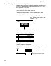
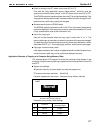
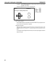
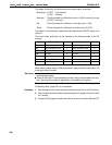
Controlling the lamps in batch
More than one lamp can be lit or flashing in batch by registering those lamps to
the same bit.
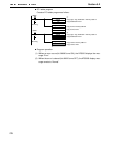
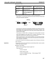
[Example of batch lighting]
Set the lamps L1 to L5 to the same bit number.
L1
L2
L3 L4 L5
L1 L2 L3
L4
L5