


Note
Appendix E
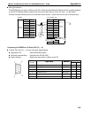
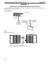
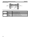
Connector Cover Assembly
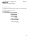
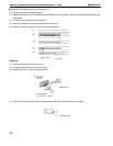
Assemble the connector covers as shown in the diagram below.
End connected to FG
Aluminum foil tape
End not connected to FG
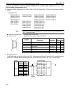
Preparing RS-232C Connector Cables
Prepare a connector cable to connect a NT600S to a HOST separated by more than 5 m so that the supplied con-
nector cable (XW2Z-500P) cannot be used. The maximum cable length is 15 m.
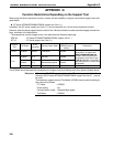
Recommended Parts
Name Model Remarks
Connector XM2A-0901 9-pin, manufactured by OMRON
Connector cover XM2S-0911 9-pin, manufactured by OMRON
Cable AWG28 5P
IFVV-SB
Multicore cable, manufactured by Fujikura, Ltd.
CO-MA-VV-SB
5P 28AWG
Multicore cable, manufactured by Hitachi Cable, Ltd.
On the other end of the cable use the type of connector and connector cover which matches the host computer
connector type.
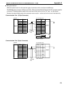
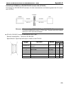
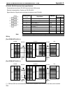
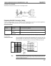
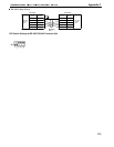
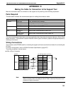
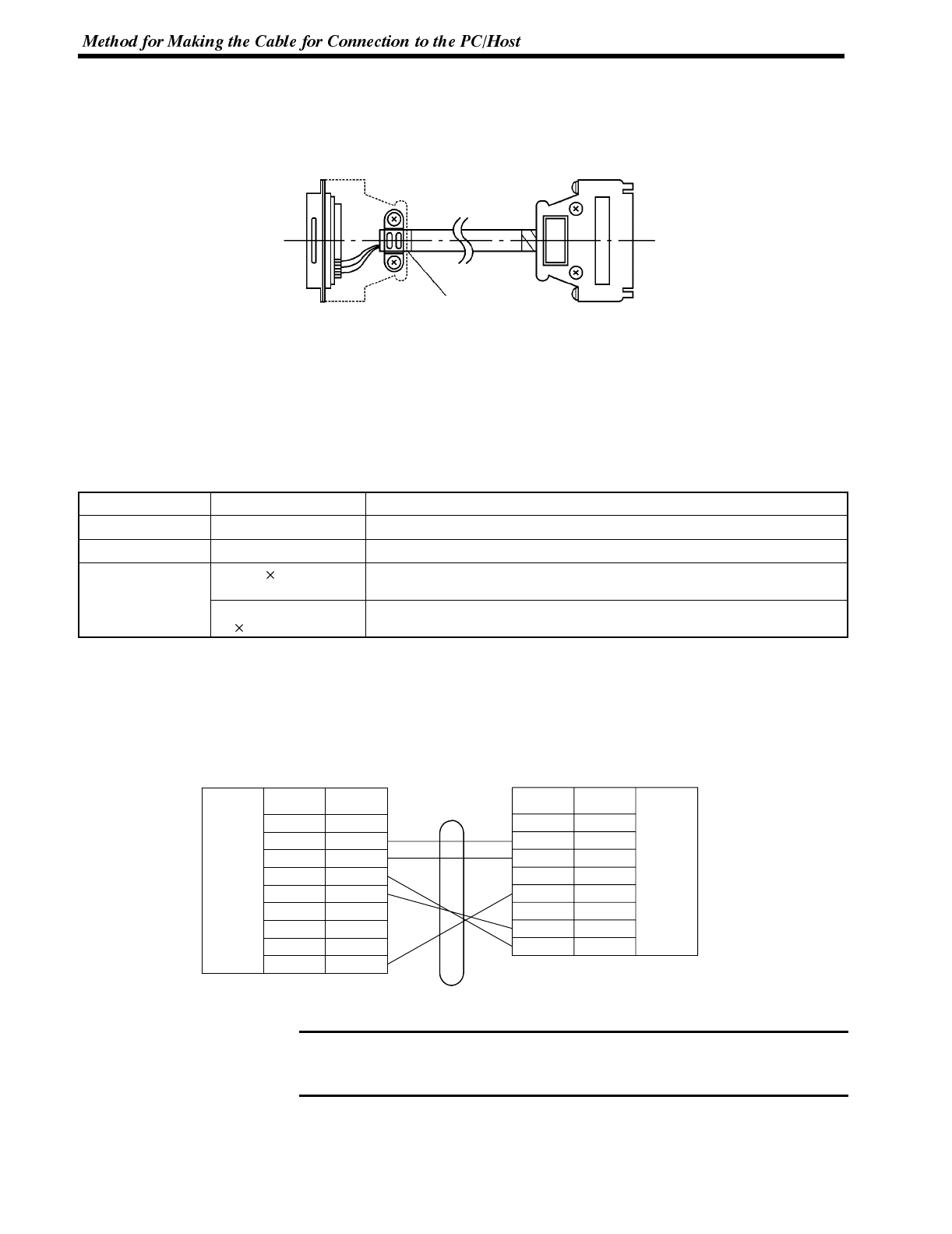
Connection For Host Only the shielded wire on the host side is connected to the connector hood. The
following diagram is for RS/CS control. If RS/CS control is not executed, RS and
CS must be short-circuited (turned over) for both the NT600S and host side.
1
2
3
4
5
6
7
8
9
Pin
number
Abbrevi-
ation
FG
SD
RD
RS
CS
+5V
--
--
SG
RS-232C
interface
Shielding
wire
NT600S HOST
RS-232C
interface
Pin
number
Abbrevi-
ation
1
2
3
4
5
6
7
--
RD
SD
--
SG
--
RS
8
CS
For some host computers the combination of pin numbers and signal names may
differ from those shown in the diagram above. Refer to the Host instruction manu-
al before wiring the connector.