


Reference
Section 4-7
Caution on pressing touch switches at 3 points
When multiple touch switches are created at the relative positions indicated in
the example below, malfunctions may occur due to the characteristics of this
switch configuration.
Be careful about the positioning when setting touch switches.
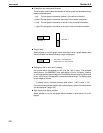
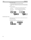
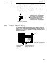
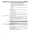
Example 1 :When switches are created at positions A and B and at the points
where the vertical and horizontal lines extending from these two points inter-
sect, i.e. points C and D:
When switches A, B, and C are switched
on at the same time, switch D is also
assumed to have been switched on due to
the configuration of the touch switches.
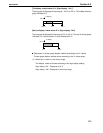
When switches A, B, and D are switched
on at the same time, switch C is also
assumed to have been switched on due to
the configuration of the touch switches.
A
C
B
D
Smallest touch switch frame
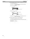
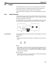
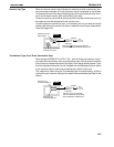
5-7-1 Functions of Touch Switches
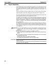
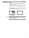
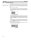
Touch switches are created using rectangular elements measuring 39 dots hori-
zontally by 49 dots vertically. A touch switch can comprise more than one touch
switch element. Up to 128 touch switches (16 horizontally x 8 vertically) can be
registered on one screen.
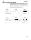
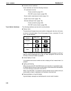
PC
A touch switch can comprise mor
e
than one touch switch element.
When the touch switch is
pressed, bit information
is sent to the PC.
(NT link/Host link/
C200H direct)
When the touch switch is pressed,
the touch switch number or bit
information is sent to the Host.
(RS-232C)
Host
STOP
39 dots
49 dots