


1
6
9
5
Correct Use
1
14
25
13
Appendix E
Connector Specifications and Wiring for OMRON Units
The combination of pin numbers to which the connecting wires are connected differs according to the connector
specifications for each unit. Check the connector specifications of the unit to be connected and make the wiring
connections for the items in the connection combination indicated below which are applicable.
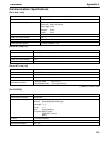
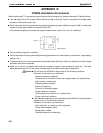
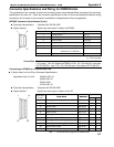
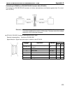
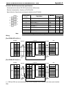
[NT600S Connector Specifications (9-pin)]
Electrical characteristics: Complies with EIA RS-232C
Signal direction: Signal input and output is relative to NT600S.
Connector Pin No. Signal Name Abbreviation
1 Frame ground FG (*1)
2 Send data SD (TXD)
3 Receive data RD (RXD)
4 Request to send RS (RTS)
5 Clear to send CS (CTS)
6 +5V Output150mA max. (211(B)-EV )
100mA max. (121(B)-EV )
+5V
9 Signal ground SG
(*1) FG is not used.
Check the current capacity of the supplied equipment before using the No.6 pin
(+5 V output). The +5 V output for NT600S is +5 V 5%, 150mA max. in the case
of ST211(B)-EV and +5 V 5%, 100 mA max. in the case of ST121(B)-EV .
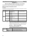
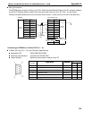
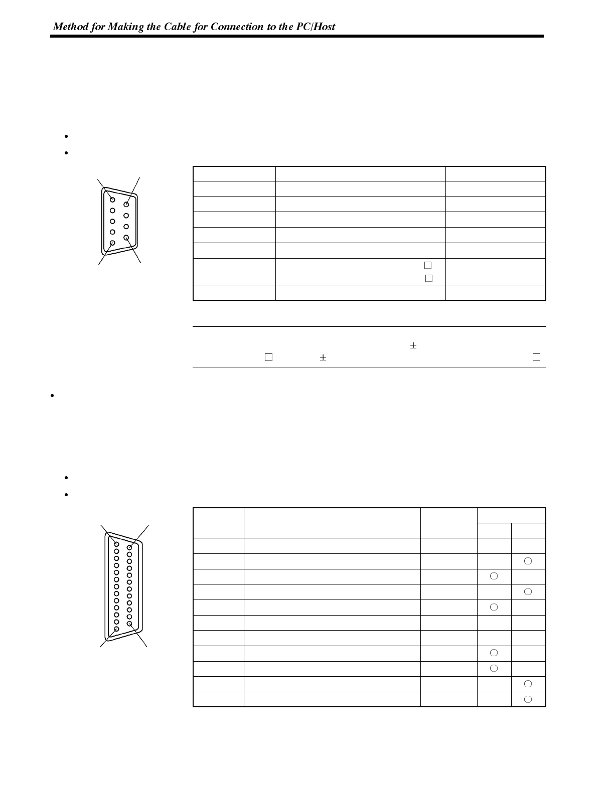
Connecting an NT600S to a C-Series Host Link
C-Series Host Link Unit 25-pin Connector Specifications
Applicable Host Link Unit: C200H-LK201-V1
C500-LK201-V1
C500-LK203
C120-LK201-V1
Electrical characteristics: Complies with EIA RS-232C
Signal direction: Signal input and output is relative to the PC.
Connector
S
i
g
n
a
l
N
a
m
e
A
b
b
r
e
v
i
a
t
i
o
n
Signal Direction
C
o
n
n
e
c
t
o
r
Pin No.
S
i
gna
l
N
ame
A
b
b
rev
i
at
i
on
Input Output
1 Frame ground FG -- --
2 Send data SD (TXD)
3 Receive data RD (RXD)
4 Request to send RS (RTS)
5 Clear to send CS (CTS)
7 Signal ground SG -- --
14 Optical connector +5V (see note 2) +5V -- --
15 Send signal element timing 2 (see note 1) ST2
17
Receive signal element timing (see note 1)
RT
20 Data terminal ready ER (DTR)
24 Data signal element timing (see note 1) ST1
Note 1. No element timing signals on C200H-LK201