


Note
Reference
Section 2-4
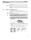
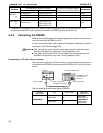
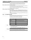
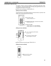
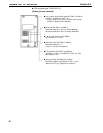
Connecting to C Series CPM1
The CPM1 is connected via an RS-232C adapter (type CPM1-CIF01).
Procure an RS-232C 9-pin type connection cable for the connection.
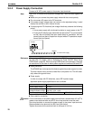
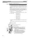
When a connector cable of 5 m or longer is required
When a connector cable of 5 m or longer is required, please make the cable. How-
ever, note that the maximum transmission distance is 15 m.
To make a connector cable, refer to Appendix E Method for Making the Cable for
Connection to the PC/Host (page 264).
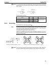
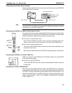
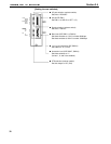
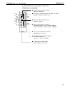
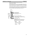
When Long-Distance Transmission is Required
When transmission over a distance exceeding the RS-232C specification is re-
quired, it can be achieved by using an RS-232C/RS-422A converter unit (type NT-
AL001) to switch to RS-422A communication (RS-485 communication cannot be
used).
For details, refer to “Appendix F Connecting to an RS-232C/RS-422A converter
unit” (page 275 of the appendix).
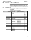
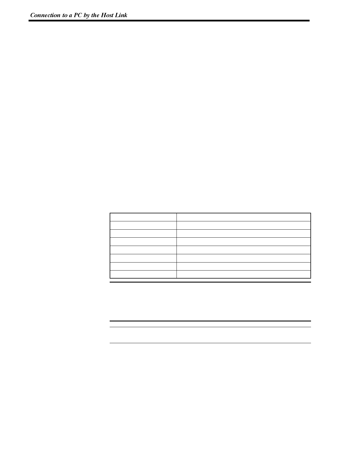
3-4-3 PC Switch Settings
When the NT600S and PC are connected to each other, set the conditions at the
PC host link unit or the CPU as given in the table below.
The following is a general description of switch settings.
Refer to the manual for respective units for the details of the switch settings.
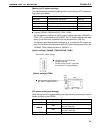
Item Switch Setting
I/O port RS-232C
Baud rate Set the same baud rate as the NT600S. (*1)
Transfer code ASCII 7 data bits, 2 stop bits
Parity Even
1-to-1/1-to-N 1-to-N (*2)
Instruction level Level 1, 2, 3
Unit # 00
*1. Set the host link baud rate at 9600 bps or 19200 bps with the memory switch
for “host link baud rate”. For the details, refer to “Selecting the Host LinkCom-
munication Speed” (page 86).
*2. The 1-to-N setting enables BCC (Block Check Character). The 1-to-N con-
nection cannot be used to connect the NT600S to a host link unit.
When using CVM1/CV series, always set “CPU execution processing (execution
control 2)” in the PC system settings to “Simultaneous processing”.