


Caution
Section 2-4
P
C
S
e
r
i
e
s
Units with Built-in Host Link Function
CPU Units Connectable Usin
g
an
C
o
n
n
e
c
t
a
b
l
e
t
o
PC Series
Host Link Unit CPU Unit
C
P
U
U
n
i
t
s
C
o
n
n
e
c
t
a
b
l
e
U
s
i
n
g
a
n
Expansion Communication Board
Connectable to
C
V
i
CV500-LK201 CV500-CPU01-EV1 CV500
CV series
(
*
)
CV500-LK201 CV1000-CPU01-EV1 CV1000
(
*
)
CV500-LK201 CV2000-CPU01-EV1 CV2000
CVM1 series
(*)
CV500-LK201
CVM1-CPU01-EV1
CVM1-CPU11-EV1
CVM1-CPU11-EV2
CVM1-CPU21-EV1
CVM1
* : Connection is not possible to the CPU units of CVM1/CV series PCs that do not have the suffix “-EV ”.
In the case of these CPU units, make the connection to NT600S by using a host link unit.
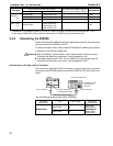
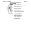
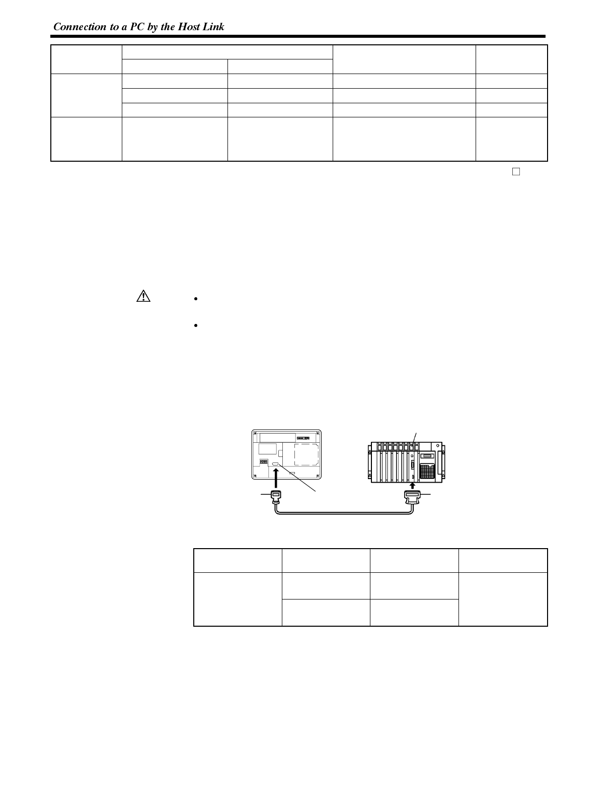
3-4-2 Connecting the NT600S
Refer to the illustrations below to select the appropriate cable for the unit connec-
tors and connect the NT600S to the PC.
To make a connector cable, refer to Appendix E Method for Making the Cable for
Connection to the PC/Host (page 264).
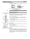
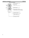
After connecting a communication cable, always secure it with the screws.
Otherwise the cable may disconnect, causing operation to fail.
The cable’s tensile load is 30 N. Do not subject it to loads greater than this.
Otherwise a discontinuity may occur, causing operation to fail.
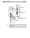
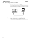
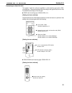
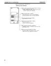
Connecting to a PC with a 25-pin Connector
Use a connector cable with a 25-pin connector on one end and a 9-pin connector
on the other end (NT600S side) to connect the NT600S to a PC with a 25-pin con-
nector.
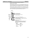
Host I/F connector
(RS-232C 9-pin type)
SYSMAC C series
PC, CVM1/CV
series PC
Host link unit/CPU unit
9-pin connector 25-pin connector
RS-232C connector cable
NT600S
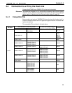
Use the following recommended cables (OMRON);
Connector
Specification
Type Cable Length
Applicable
Host Link Unit
2
5
p
i
n
t
o
9
p
i
n
XW2Z-200S 2m
C500-LK203
C500-LK201-V1
C
1
2
0
L
K
2
0
1
V
1
25-pin to 9-pin
XW2Z-500S 5m
C120-LK201-V1
C200H-LK201
CV500-LK201