


Appendix E
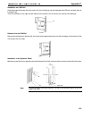
Wiring Connections
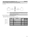
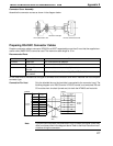
CVM1/CV-series host link units have two types of connector, which must be wired differently.
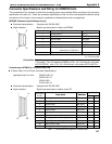
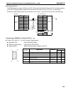
The NT600S does not use pin 4 (RS) or pin 5 (CS). Either short the RS and CS pins of the PC connector together
or set the CTS setting selector switch at the rear face of the host link unit to “0V” (see in the figure).
Connect the cable shielding wire to the connector cover and pin 1 at the host link unit end of the cable only.
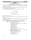
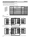
Communication Port 1 (25-pin Connector)
1
2
3
4
5
6
7
8
9
Pin
number
Abbrevi-
atioon
FG
SD
RD
RS
CS
+5V
--
--
SG
RS-232C
interface
RS-232C
interface
Pin
number
Abbrevi-
atioon
1
2
3
4
5
6
7
8
--
FG
SD
RD
RS
CS
--
SG
--
--
Shielding
wire
25-pin connector
NT600S PC (host link unit)
--
--
--
ER
--
--
--
20
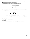
Communication Port 2 (9-pin Connector)
1
2
3
4
5
6
7
8
9
Pin
number
Abbrevi-
atioon
FG
SD
RD
RS
CS
+5V
--
--
SG
RS-232C
interface
Shielding
wire
NT600S PC (host link unit)
RS-232C
interface
Pin
number
Abbrevi-
atioon
2
3
4
5
6
7
--
9
FG
SD
RD
RS
CS
--
CD
--
SG
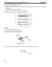
9-pin connector
Connector cover