


1
14
25
13
1
6
9
5
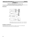
Appendix E
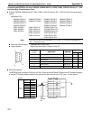
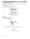
Wiring Connections
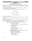
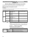
The NT600S does notuse pin 4(RS) or pin 5 (CS). Short theRS andCS pins of the PC connector together (see
in the figure).
Connect the cable shielding wire to the connector cover and pin 1 at both the NT600S and CPU ends of the cable.
1
2
3
4
5
6
7
8
9
Pin
number
Abbrevi-
atioon
FG
SD
RD
RS
CS
+5V
--
--
SG
RS-232C
interface
Shielding
wire
NT600S PC CPU
RS-232C
interface
Pin
number
Abbrevi-
atioon
1
2
3
4
5
6
7
--
--
FG
SD
RD
RS
CS
--
SG
--
--
9-pin connector
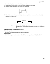
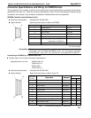
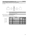
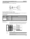
Connecting an NT600S to a CVM1/CV-Series Host Link Unit
CVM1/CV-Series Host Link Unit Connector Specifications
Applicable host link unit: CV500-LK201
Electrical characteristics: Complies with EIA RS-232C
Signal direction: Signal input and output is relative to the PC.
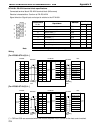
Communication Port 1 (25-pin Connector)
Connector Pin
S
i
g
n
a
l
N
a
m
e
A
b
b
r
e
v
i
a
t
i
o
n
Signal Direction
C
o
n
n
e
c
t
o
r
P
i
n
No.
S
i
gna
l
N
ame
A
b
b
rev
i
at
i
on
Input Output
Connector cover
Frame ground FG -- --
1 Frame ground FG -- --
2 Send data SD (TXD)
3 Receive data RD (RXD)
4 Request to send RS (RTS)
5 Clear to send CS (CTS)
7 Signal ground SG (GND) -- --
8 Carrier detected CD (DCD)
14 Optical connector +5V +5V
20 Data terminal ready ER (DTR)
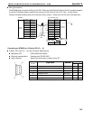
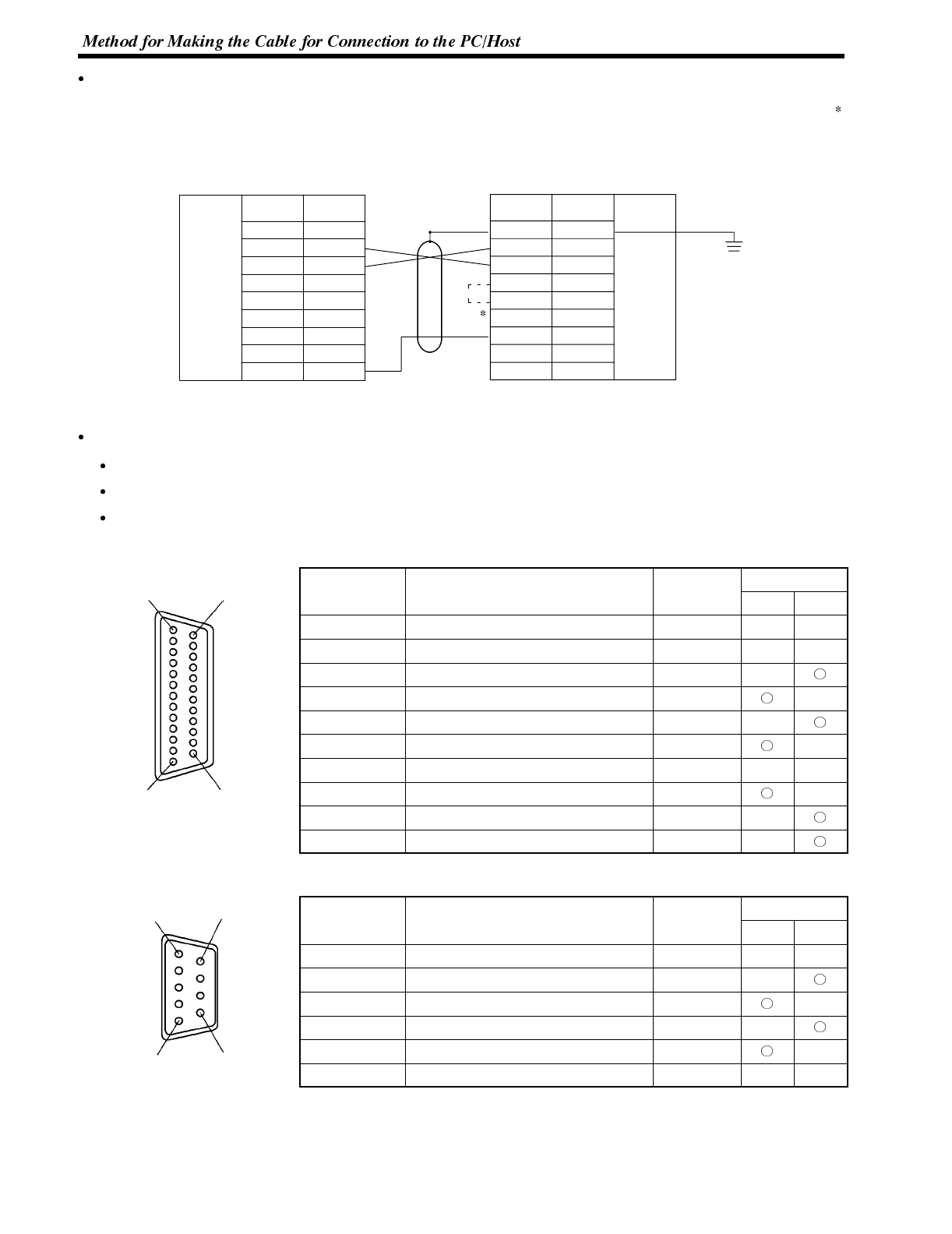
Communication Port 2 (9-pin Connector)
Connector
S
i
g
n
a
l
N
a
m
e
A
b
b
r
e
v
i
a
t
i
o
n
Signal Direction
C
o
n
n
e
c
t
o
r
Pin No.
S
i
gna
l
N
ame
A
b
b
rev
i
at
i
on
Input Output
Connector cover
Frame ground FG -- --
2 Send data SD (TXD)
3 Receive data RD (RXD)
4 Request to send RS (RTS)
5 Clear to send CS (CTS)
9 Signal ground SG (GND) -- --