


Reference
Section 2-1
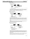
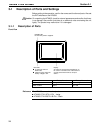
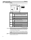
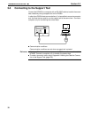
Rear View
Lid of CFL case
The backlight unit and battery
mounting holder are installed
underneath this lid.
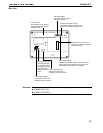
Contrast control (ST121 only)
Use a fine flat-blade screwdriver. Turn
clockwise to increase the brightness.
DIP switch (SW2)
Set various system statuses
with these switches.
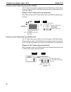
Grounding terminal
Grounding terminal
for exclusive class 3
grounding to prevent
malfunction due to
noise and electric
shock.
Reset switch (SW1)
Initializes the NT600S statuses. Note that for the
image data memory and the memory switch, the
status before the initialization is retained.
Host I/F tool connector
Connect the cable from a
PC/Host or support tool here.
Power input terminals
Connect the power to the
NT600S at these terminals.
+
24VDC
Host interface unit connector
Connect the cable from the host
interface unit here.
Contrast control is available only for the following models:
NT600S-ST121-EV
NT600S-ST121B-EV