


74
Wiring Module Connectors Section 3-3
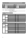
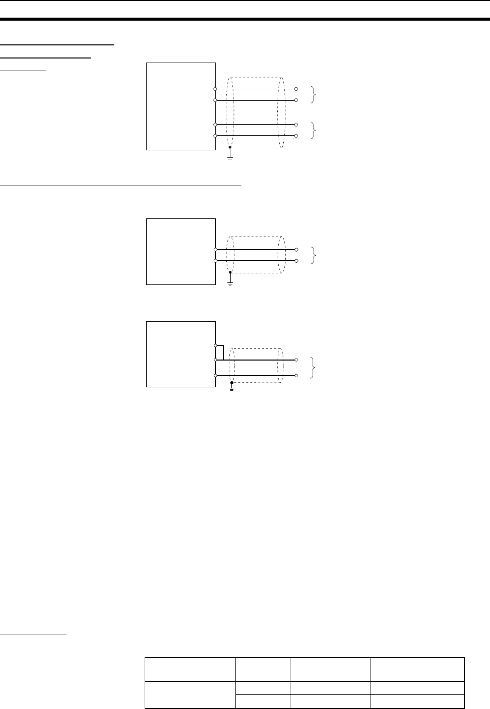
Connecting Analog
Outputs (FQM1-
MMA21)
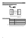
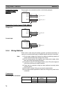
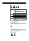
Output signals are connected as shown in the following diagram.
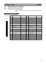
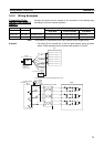
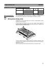
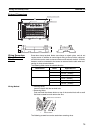
Connecting Analog Inputs (FQM1-MMA21)
Voltage Input
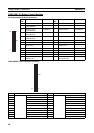
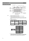
Current Input
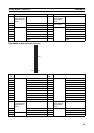
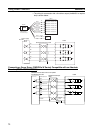
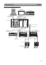
3-3-4 Wiring Methods
Either make a cable using the special connector (purchased separately), or
connect to a terminal block using an OMRON special cable with a connector.
Note (1) Do not apply voltages that exceed the maximum switching capacity of
output circuits and the input voltage of I/O circuits.
(2) Do not mistake positive and negative when wiring power supply, where
there are positive and negative terminals.
(3) To conform to the EC Low Voltage Directive, use a DC power supply for
I/O that has reinforced or double insulation.
(4) Check that the connector wiring has been performed correctly before
supplying power.
(5) Do not pull on cables. Doing so may result in disconnection.
(6) Do not bend cables beyond their natural limit. Doing so may result in dis-
connection.
Connectors
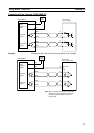
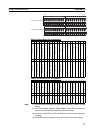
Connecting MIL Connectors
Pin No.
Analog output 2
Shield
38 (V2+)
40 (V2−)
+
−
Analog output 1
37 (V1+)
39 (V1−)
+
−
40-pin connector
FQM1-MMA21
Pin No.
Shield
Analog input
33 (V1+)
35 (V1−)
+
−
Special I/O connector
FQM1
Pin No.
Shield
Analog input
33 (V1+)
35 (V1−)
+
−
Special I/O connector
FQM1
34 Current input
Connector type Number of
pins
Ordering as a set
(OMRON)
DDK Ltd.
Pressure welded 26 pins XG4M-2630-T FRC5-A026-3T0S
40 pins XG4M-4030-T FRC5-A040-3T0S