


127
Serial Communications Section 6-1
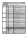
Host Link Commands The following table lists the Host Link commands. Refer to the C-series Host
Link Units System Manual (W143) for details.
Type Header
code
Name Function
Reading I/O
memory
RR CIO AREA READ Reads the contents of the specified number of CIO Area
words, starting from the specified word.
RC PV READ Reads the contents of the specified number of timer/counter
PVs (present values), starting from the specified
timer/counter.
RG T/C STATUS READ Reads the status of the Completion Flags of the specified
number of timers/counters, starting from the specified
timer/counter.
RD DM AREA READ Reads the contents of the specified number of DM Area
words, starting from the specified word.
RJ AR AREA READ Reads the contents of the specified number of Auxiliary Area
words, starting from the specified word.
Writing I/O
memory
WR CIO AREA WRITE Writes the specified data (word units only) to the CIO Area,
starting from the specified word.
WC PV WRITE Writes the PVs (present values) of the specified number of
timers/counters, starting from the specified timer/counter.
WD DM AREA WRITE Writes the specified data (word units only) to the DM Area,
starting from the specified word.
WJ AR AREA WRITE Writes the specified data (word units only) to the Auxiliary
Area, starting from the specified word.
Changing
timer/counter
set values
R# SV READ 1 Reads the 4-digit BCD constant or word address in the SV of
the specified timer/counter instruction.
R$ SV READ 2 Searches for the specified timer/counter instruction beginning
at the specified program address and reads the 4-digit con-
stant or word address of the SV.
R% SV READ 3 Searches for the specified timer/counter instruction beginning
at the specified program address and reads the 4-digit BCD
constant or word address of the SV.
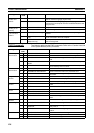
Status com-
mands
W# SV CHANGE 1 Changes the 4-digit BCD constant or word address in the SV
of the specified timer/counter instruction.
W$ SV CHANGE 2 Searches for the specified timer/counter instruction beginning
at the specified program address and changes the 4-digit con-
stant or word address of the SV.
W% SV CHANGE 3 Searches for the specified timer/counter instruction beginning
at the specified program address and changes the 4-digit con-
stant or word address of the SV.
MS STATUS READ Reads the operating status of the Coordinator Module (operat-
ing mode, force-set/reset status, fatal error status).
SC STATUS CHANGE Changes the Coordinator Module’s operating mode.
MF ERROR READ Reads errors in the Coordinator Module (non-fatal and fatal).
Force-set/reset
commands
KS FORCE SET Force-sets the specified bit.
KR FORCE RESET Force-resets the specified bit.
FK MULTIPLE FORCE
SET/RESET
Force-sets, force-resets, or clears the forced status of the
specified bits.
KC FORCE SET/RESET CAN-
CEL
Cancels the forced status of all force-set and force-reset bits.
Reading model
codes
MM PLC MODEL READ Reads the model type of the FQM1.
Test commands TS TEST Returns, unaltered, one block of data transmitted from the
host computer.