


39
Motion Control Modules Section 2-4
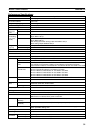
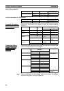
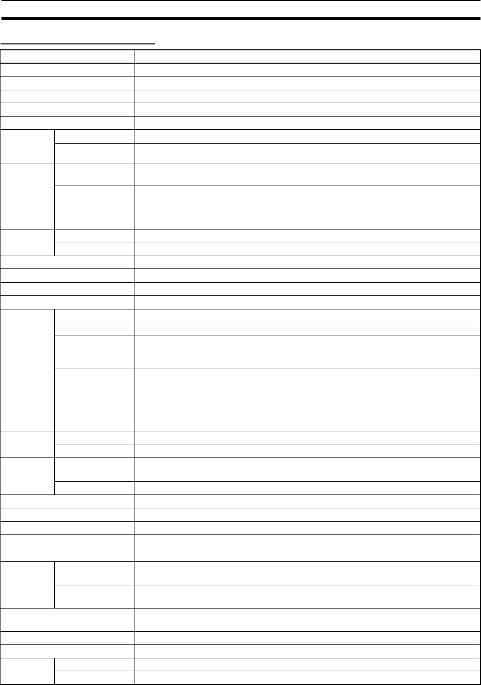
Performance Specifications
Item Specifications
Control method Stored program
I/O control method Cyclic scan
Programming language Ladder diagram
Instruction length 1 to 7 steps per instruction
Number of instructions Approx. 270
Instruction
execution
time
Basic instructions 0.1 µs min.
Special instructions 0.3 µs min.
Common
processing
time (over-
head)
MMP21 Sync Mode: 250 µs
ASync Mode: 190 µs
MMA21 Sync Mode: 340 µs
ASync Mode: 280 µs
Each analog input when analog output is disabled: 190 µs
When analog output disabled: 230 µs
Program
capacity
Ladder 5 Ksteps
Comment storage None
Number of tasks Cyclic tasks: 1, interrupt tasks: 50
Subroutines 256
JMP instructions 256
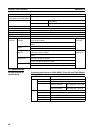
Number of basic I/O 20 per Module
CIO Area Input Bit Area 12 bits (CIO 0000): CIO 0000.00 to CIO 0000.11
Output Bit Area 8 bits (CIO 0001): CIO 0001.00 to CIO 0001.07
Cyclic Refresh Bit
Area
160 bits (10 words): CIO 0100 to CIO 0109
Input refresh for Coordinator to Motion Control Module: CIO 0100 to CIO 0104
Output refresh for Motion Control Module to Coordinator Module: CIO 0105 to CIO 0109
Synchronous Data
Link Bit Area
320 bits (20 words): CIO 0200 to CIO 0219
Sent from Coordinator Module: CIO 0200 to CIO 0203
Sent from Motion Control Module #1: CIO 0204 to CIO 0207
Sent from Motion Control Module #2: CIO 0208 to CIO 0211
Sent from Motion Control Module #3: CIO 0212 to CIO 0215
Sent from Motion Control Module #4: CIO 0216 to CIO 0219
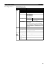
Work Area CIO Area 3,584 bits: CIO 0002 to CIO 0099, CIO 0110 to CIO 0199, and CIO 0220 to CIO 0255
WR Area 4,096 bits: W000 to W255
Auxiliary
Area
Read/Write Read only: 5,568 bits, A000 to A099 and A200 to A447
Read/write: 3,232 bits, A448 to A649
Error Log 100 words: A100 to A199 (20 records)
Temporary Area 16 bits: TR0 to TR15
Holding Area None
Timer Area 256 timers: T0000 to T0255 (1-ms, 10-ms, and 100-ms timers)
Counter Area 256 counters C0000 to C0255 (decrementing counters and reversible counters)
Note Status not retained when power turned OFF.
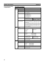
DM Area Read/write (not
retained)
30 Kwords: D00000 to D29999 (Status not retained when power is turned OFF.)
Read/write
(retained)
2,768 words: D30000 to D32767 (Retained by super capacitor)
System Setup System Setup Area (Coordinator Module/Motion Control Module settings),
motion parameter setting area
Index Registers IR0 and IR1 used with JSB instruction
Data Registers None
Interrupt
Functions
Input interrupts 4 (with adjustment down mode)
Timer interrupts 1(Scheduled or one-shot interrupt)