


77
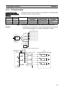
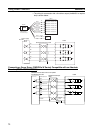
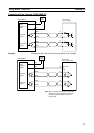
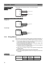
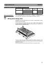
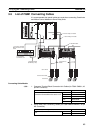
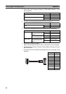
Wiring Servo Relay Units Section 3-4
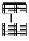
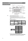
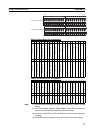
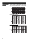
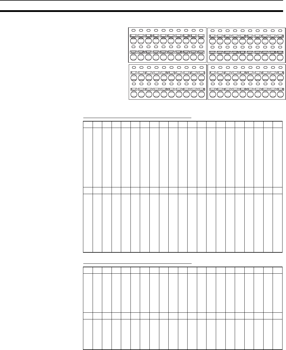
Upper Terminal Block Pin Arrangement
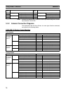
Lower Terminal Block Pin Arrangement
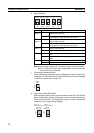
Note (1) Allocated when connecting an FQM1-MMA21 Analog I/O Motion Control
Module.
(2) Used as the power supply for FQM1-MMP21 pulse outputs or SEN out-
puts for Servo Drivers compatible with absolute encoder.
(3) IN4 to IN11 and OUT0 to OUT7 are used for the servo control signal pow-
er supply.
(4) IN0 to IN3 (interrupt inputs) are used for the latch input power supply.
No.6061626364656667686970717273747576777879
Signal name
5 V (See note 2.)
Latch signal input 1
Latch signal input 2
CNT1 phase A LD + input
CNT1 phase B LD + input
Servo # 1 phase Z LD + output
Voltage input (+) (See note 1.)
Servo #1 ALM
Servo #1 TGON
IN4
IN5
IN6
IN7
---
Servo #1 RUN
Servo #1 RESET
Servo #1 ECRST
Servo #1 MING
TXD+
RXD+
No.4041424344454647484950515253545556575859
Signal name
0 V
Latch signal 1 common (0 V)
Latch signal 2 common (0 V)
CNT1 phase A LD
−
CNT1 phase B LD
−
Servo #1 phase Z LD
−
Voltage input (
−
) (See note 1.)
Servo #1 INP
Common (0 V)
Common (0 V)
Common (0 V)
Common (0 V)
Common (0 V)
---
OUT0
OUT1
OUT2
OUT3
TXD
−
RXD
−
No.2021222324252627282930313233343536373839
Signal name
+24 V (See note 3.)
+24 V (See note 4.)
IN0
IN1
IN2
IN3
---
Servo #2 ALM
Servo #2 TGON
IN8
IN9
IN10
IN11
---
Servo #2 RUN
Servo #2 RESET
Servo #2 ECRST
Servo #2 MING
---
FG
No.012345678910111213141516171819
Signal name
0 V
0 V
Common (0 V)
Common (0 V)
Common (0 V)
Common (0 V)
---
Servo #2 INP
Common (0 V)
Common (0 V)
Common (0 V)
Common (0 V)
Common (0 V)
---
OUT4
OUT5
OUT6
OUT7
---
FG
60 79
0 1 2 3 4 5 6 7 8 9
0 1 2 3 4 5 6 7 8 9
0 1 2 3 4 5 6 7 8 9
0 1 2 3 4 5 6 7 8 9
0 1 2 3 4 5 6 7 8 9
0 1 2 3 4 5 6 7 8 9
0 1 2 3 4 5 6 7 8 9
0 1 2 3 4 5 6 7 8 9
019
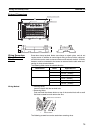
Upper terminal block
Lower terminal block