


347
System Setup, Auxiliary Area Allocations, and Built-in I/O Allocations Appendix C
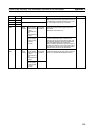
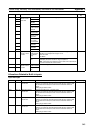
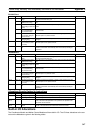
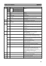
RS-232C Port
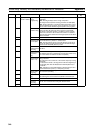
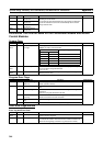
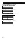
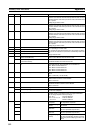
RS-422A Port
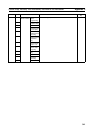
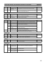
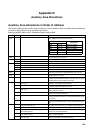
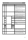
Allocations Directly Related to Instructions
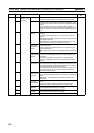
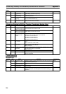
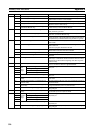
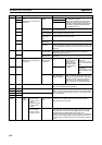
Built-in I/O Allocations
The Coordinator Module and Motion Control Modules all have built-in I/O. The I/O Area allocations to the con-
tacts on the Modules are given in the following tables.
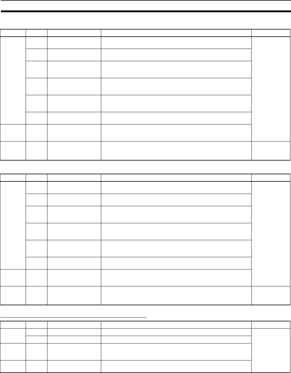
Address Bits Name Function Controlled by
A410 02 to 05 RS-232C Port Error
Flags
Indicates the status of the error flags that turn ON when an error has
occurred at the RS-232C port.
Module
08 RS-232C Port Commu-
nications Error Flag
Turns ON when a communications error has occurred at the RS-232C
port.
09 RS-232C Port Send
Ready Flag (no-protocol
mode)
Turns ON when the RS-232C port is ready to send data in no-protocol
mode.
10 RS-232C Port Recep-
tion Completed Flag
(no-protocol mode)
Turns ON when the RS-232C port has completed the reception in no-
protocol mode.
11 RS-232C Port Recep-
tion Overflow Flag (no-
protocol mode)
Turns ON when a data overflow occurred during reception through the
RS-232C port in no-protocol mode.
15 RS-232C Port Settings
Changing Flag
Turns ON while the RS-232C port’s communications settings are being
changed.
A411 00 to 15 RS-232C Port Recep-
tion Counter (no-proto-
col mode)
Indicates (in binary) the number of bytes of data received when the
RS-232C port is in no-protocol mode.
A502 00 RS-232C Port Restart
Bit
Turn this bit ON to restart the RS-232C port.
This bit is turned OFF automatically when the restart processing is
completed.
User
Address Bits Name Function Controlled by
A414 02 to 05 RS-422A Port Error
Flags
Indicates the status the error flags that turn ON when an error has
occurred at the RS-422A port.
Module
08 RS-422A Port Commu-
nications Error Flag
Turns ON when a communications error has occurred at the RS-422A
port.
09 RS-422A Port Send
Ready Flag (no-protocol
mode)
Turns ON when the RS-422A port is ready to send data in no-protocol
mode.
10 RS-422A Port Recep-
tion Completed Flag
(no-protocol mode)
Turns ON when the RS-422A port has completed the reception in no-
protocol mode.
11 RS-422A Port Recep-
tion Overflow Flag (no-
protocol mode)
Turns ON when a data overflow occurred during reception through the
RS-422A port in no-protocol mode.
15 RS-422A Port Settings
Changing Flag
Turns ON while the RS-422A port’s communications settings are being
changed.
A415 00 to 15 RS-422A Port Recep-
tion Counter (no-proto-
col mode)
Indicates (in binary) the number of bytes of data received when the
RS-422A port is in no-protocol mode.
A502 02 RS-422A Port Restart
Bit
Turn this bit ON to restart the RS-422A port.
This bit is turned OFF automatically when the restart processing is
completed.
User
Address Bits Name Function Controlled by
A200 11 First Cycle Flag ON for one cycle after FQM1 operation begins. Module
12 Step Flag ON for one cycle when step execution is started with STEP(008).
A510 to
A514
00 to 15 Macro Area Input Words Before the subroutine specified in MCRO(099) is executed, the con-
tents of the five words specified in the operand to be passed to the
subroutine are stored here.
A515 to
A519
00 to 15 Macro Area Output
Words
After the subroutine specified in MCRO(099) has been executed, the
results of the subroutine are transferred to these five words.