


67
Wiring Module Connectors Section 3-3
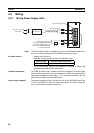
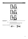
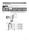
3-3 Wiring Module Connectors
3-3-1 Connector Pin Arrangement
The following tables provide the connector pin arrangement for FQM1 Mod-
ules.
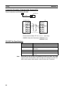
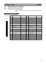
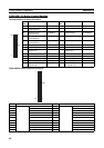
FQM1-CM001 Coordinator Module
General-purpose I/O 40-pin Connector
Pin
No.
Name Address Pin
No.
Name Address
1 External input 0 CIO 0000.00 2 External input 8 CIO 0000.08
3 External input 1 CIO 0000.01 4 External input 9 CIO 0000.09
5 External input 2 CIO 0000.02 6 External input 10 CIO 0000.10
7 External input 3 CIO 0000.03 8 External input 11 CIO 0000.11
9 External input 4 CIO 0000.04 10 External input 12 CIO 0000.12
11 External input 5 CIO 0000.05 12 External input 13 CIO 0000.13
13 External input 6 CIO 0000.06 14 External input 14 CIO 0000.14
15 External input 7 CIO 0000.07 16 External input 15 CIO 0000.15
17 Common for external
inputs 0 to 7
--- 18 Common for external
inputs 8 to 15
19 External output 0 CIO 0001.00 20 External output 4 CIO 0001.04
21 External output 1 CIO 0001.01 22 External output 5 CIO 0001.05
23 External output 2 CIO 0001.02 24 External output 6 CIO 0001.06
25 External output 3 CIO 0001.03 26 External output 7 CIO 0001.07
27 Common for external
outputs 0 to 8
28 Power supply for exter-
nal outputs 0 to 8
29 Not used. 30 Not used.
31 Not used. 32 Not used.
33 SDA− (RS-422A) 34 RDA− (RS-422A)
35 SDB+ (RS-422A) 36 RDB+ (RS-422A)
37 Not used. 38 Not used.
39 Not used. 40 Not used.
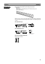
1
39
2
40
CN1