


165
Pulse Inputs Section 7-5
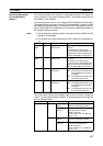
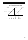
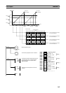
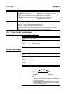
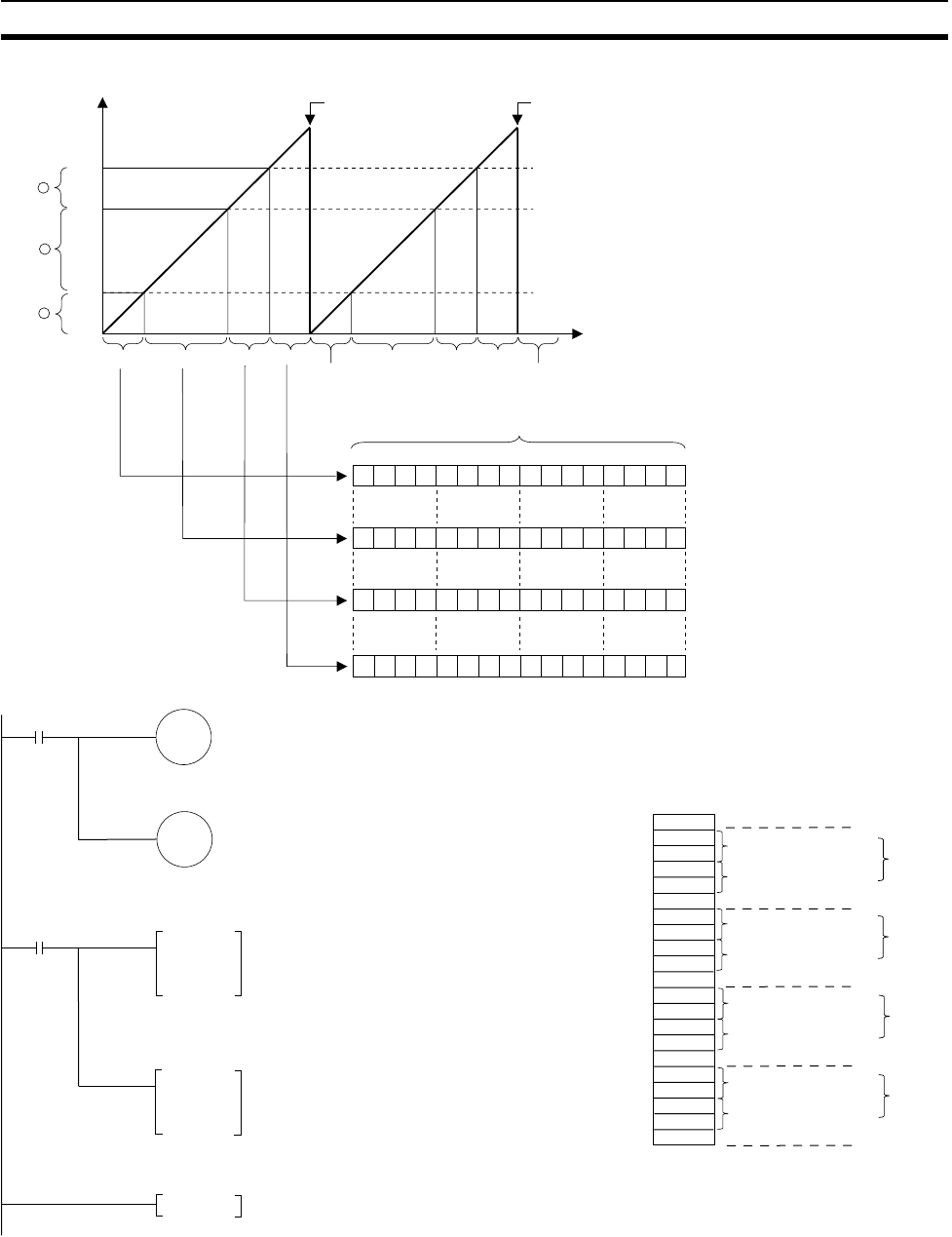
Range
High-speed
Counter PV
Time
Content of A612
3
10000
Range
2
7500
Range
1
2500
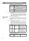
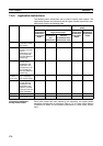
A612: 0001 hex 0002 hex 0004 hex 0008 hex
0001 hex
0002 hex
0004 hex
0008 hex
0001 hex
PV reset on
phase-Z signal
PV reset on
phase-Z signal
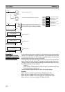
15 14 13 12 11 10 9 8 6 5 4 3 2710
0000 00000001
0000 00000010
0000 00001000
Internal bit pattern
(0001 hex) Content is transferred to CIO 0001
to turn ON CIO 0001.00.
(0002 hex) Content is transferred to CIO 0001
to turn ON CIO 0001.01.
(0004 hex) Content is transferred to CIO 0001
to turn ON CIO 0001.02.
0000 00010000
0000
0000
0000
0000
(0008 hex) Content is transferred to CIO 0001
to turn ON CIO 0001.03.
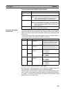
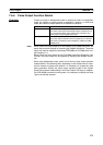
0
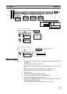
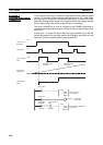
CTBL
#0001
#0001
D00000
Continually compares the high-speed counter PV
from high-speed counter 1 with the specified
ranges.(In this case, the comparison table
begins at D00000.)
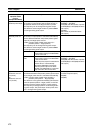
D00000 0 0 0 4
D00001 0 0 0 0
D00002 0 0 0 0
D00003 2 5 0 0
D00004 0 0 0 0
D00005 0 0 0 1
D00006 2 5 0 1
D00007 0 0 0 0
D00008 7 5 0 0
D00009 0 0 0 0
D00010 0 0 0 2
D00011 7 5 0 1
D00012 0 0 0 0
D00013 0 0 0 0
D00014 0 0 0 1
D00015 0 0 0 4
D00016 0 0 0 1
D00017 0 0 0 1
D00018 F F F F
D00019 7 F F F
D00020 0 0 0 8
A610.00
Turns ON the High-speed Counter 1 Reset Bit.
P_On
(Always ON)
Reset Bit
A610.01
Starts high-speed counter 1.
Start high-speed
counter.
P_On
(Always ON)
END
MOV
A613
0001
Transfers the internal bit pattern from A613 to
CIO 0001.
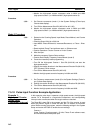
4 comparison conditions
Lower limit A 0
Upper limit A 2500
Range A
Bit pattern
Lower limit B 2501
Upper limit B 7500
Range B
Bit pattern
Lower limit C 7501
Upper limit C 10000
Range C
Bit pattern
Lower limit D 10001
Upper limit D 7FFFFFFF
Range D
Bit pattern