


143
Input Interrupts Section 7-3
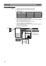
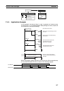
Counter Mode
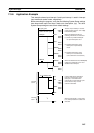
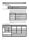
7-3-5 Using Input Interrupts
Input Interrupt Mode Procedure
1,2,3... 1. Determine which input interrupt number will be used.
2. Wire the input.
3. Make the necessary System Setup settings.
• Set the Interrupt Input Settings (set whether an interrupt will be generated
when the input turns ON, OFF, or both).
Note The default input setting is for a normal input.
4. Create the necessary ladder programming.
• Use the MSKS(690) instruction (SET INTERRUPT MASK) to enable the
input as an interrupt input.
• Create the interrupt task program.
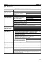
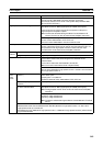
Item Specification
Interrupt condition Counter decremented from SV each time input contacts 0 to 3
(CIO 0000.00 to CIO 0000.03) turn ON, OFF, or both and PV
reaches 0.
Note Set the interrupt condition in the System Setup.
Interrupt task num-
bers
CIO 0000.00 to CIO 0000.03: Interrupt tasks 000 to 003
(fixed)
Counter operation Decrementing pulse input
Input method Single phase
Counting speed 2 kHz
Counter value 0000 to FFFF hex
Counter PV storage Input interrupts 0 to 3 (CIO 0000.00 to CIO 0000.03):
A524 to A527
Counter SV storage Input interrupts 0 to 3 (CIO 0000.00 to CIO 0000.03):
A520 to A523
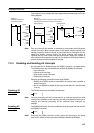
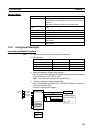
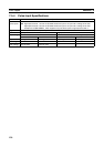
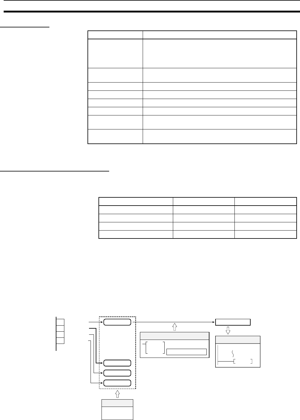
Input Allocated input bit Interrupt task number
External interrupt input 0 CIO 0000.00 000
External interrupt input 1 CIO 0000.01 001
External interrupt input 2 CIO 0000.02 002
External interrupt input 3 CIO 0000.03 003
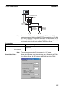
Interrupt
input
0 CIO 0000.00
1
CIO 0000.01
2
CIO 0000.02
3
CIO 0000.03
Interrupt input 0
MSKS Interrupt control
Enable interrupt inputs
Ladder program
Interrupt input
settings
System Setup
Interrupt generated.
Execute specified task.
END
Interrupt input 1
Interrupt input 2
Interrupt input 3