


36
Coordinator Module Section 2-3
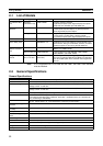
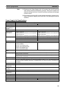
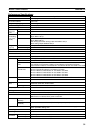
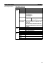
CIO Area Input Bit Area 16 bits (CIO 0000): CIO 0000.00 to CIO 0000.15
Output Bit Area 8 bits (CIO 0001): CIO 0001.00 to CIO 0001.07
Cyclic Refresh Bit
Area
640 bits (40 words): CIO 0100 to CIO 0139
Refresh words for Motion Control Module # 1: CIO 0100 to CIO 0109
Refresh words for Motion Control Module # 2: CIO 0110 to CIO 0119
Refresh words for Motion Control Module # 3: CIO 0120 to CIO 0129
Refresh words for Motion Control Module # 4: CIO 0130 to CIO 0139
Synchronous Data
Link Bit Area
320 bits (20 words): CIO 0200 to CIO 0219
Sent from Coordinator Module: CIO 0200 to CIO 0203
Sent from Motion Control Module #1: CIO 0204 to CIO 0207
Sent from Motion Control Module #2: CIO 0208 to CIO 0211
Sent from Motion Control Module #3: CIO 0212 to CIO 0215
Sent from Motion Control Module #4: CIO 0216 to CIO 0219
Serial PLC Link Bit
Area
320 bits (20 words): CIO 0080 to CIO 0099
CIO 0080 to CIO 0089: CJ1M to FQM1
CIO 0090 to CIO 0099: FQM1 to CJ1M
Can be connected as a Serial PLC Link slave to host PLC (CJ1M).
Work Bit Areas CIO Area 2,784 bits: CIO 0002 to CIO 0079, CIO 0140 to CIO 0199, and CIO 0220 to 0255
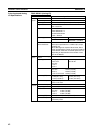
Work Area 4,096 bits: W000 to W255
Auxiliary Area Read/Write Read only: 5,568 bits: A000 to A099 and A200 to A447
Read/write: 3,232 bits: A448 to A649
Error Log 100 words: A100 to A199 (20 records)
Temporary Area 16 bits: TR0 to TR15
Holding Area None
Timer Area 256 timers: T0000 to T0255 (1-ms, 10-ms, and 100-ms timers)
Counter Area 256 counters: C0000 to C0255 (decrementing counters and reversible counters)
Note Status not retained when power turned OFF.
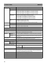
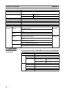
DM Area Read/Write (not
retained)
30 Kwords: D00000 to D29999 (Status not retained when power is turned OFF.)
Read/Write
(retained)
2,768 words: D30000 to D32767 (Status retained in flash memory. Not retained if
written by a ladder program, but retained in flash memory if written using the CX-
Programmer.)
System Setup System Setup area (Coordinator Module/Motion Control Module settings and
peripheral service settings), peripheral service setting area
Index Registers IR0 and IR1 used with JSB instruction.
Data Registers None
Interrupt Func-
tions
Input interrupts None
Timer interrupts 1 (Scheduled or one-shot interrupt)
Power interruption hold function
(momentary power interruption)
Super capacitor
Memory backup Super capaci-
tor backup
Error log
Flash memory User programs, System Setup, part of DM Area
Trace memory 4,000 words
Peripheral servicing Servicing for devices connected to peripheral port (only CX-Programmer), RS-
232C port (Host Links, no-protocol communications, NT Links, and Serial PLC
Links (slave)), and RS-422A port (for Servo Driver)
Self-diagnosis function CPU errors (WDT) and memory errors
Program check Programs checked from the CX-Programmer.
Super-capacitor backup time Approximately 100 hours at 25°C
Clock None
Fixed Power OFF detection time AC: 10 to 25 ms (variable)
User-set Power OFF detection time 0 to 10 ms
Item Specifications