


352
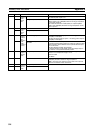
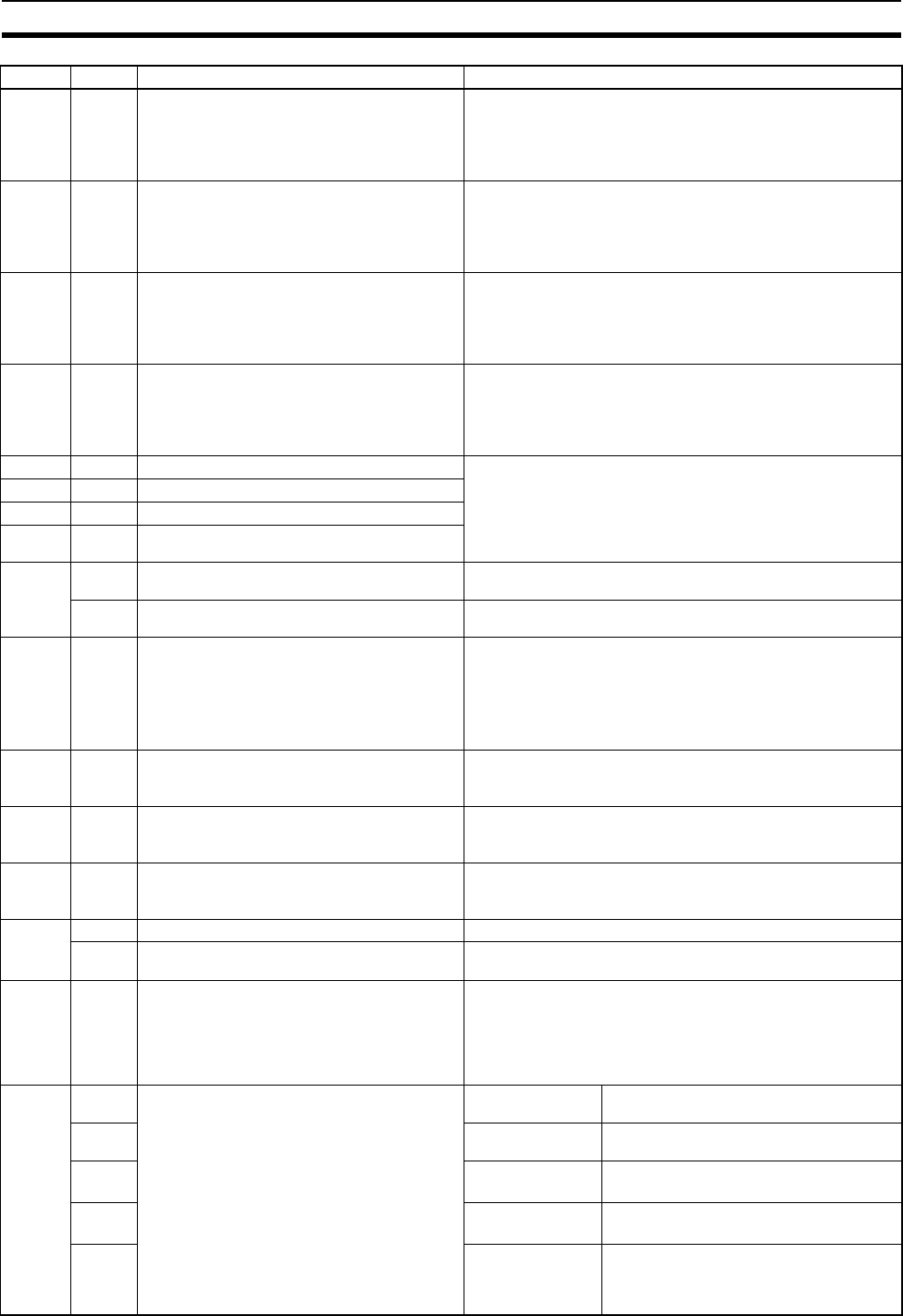
Auxiliary Area Allocations Appendix D
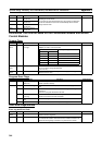
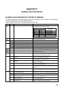
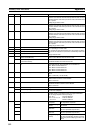
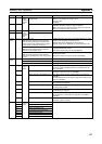
A520 00 to 15 Interrupt Counter 0 Counter SV Used for interrupt input 0 in counter mode.
Sets the count value at which the interrupt task will start. Interrupt
task 000 will start when interrupt counter 0 has counted this num-
ber of pulses.
Setting range: 0000 to FFFF
A521 00 to 15 Interrupt Counter 1 Counter SV Used for interrupt input 1 in counter mode.
Sets the count value at which the interrupt task will start. Interrupt
task 001 will start when interrupt counter 1 has counted this num-
ber of pulses.
Setting range: 0000 to FFFF
A522 00 to 15 Interrupt Counter 2 Counter SV Used for interrupt input 2 in counter mode.
Sets the count value at which the interrupt task will start. Interrupt
task 002 will start when interrupt counter 2 has counted this num-
ber of pulses.
Setting range: 0000 to FFFF
A523 00 to 15 Interrupt Counter 3 Counter SV Used for interrupt input 3 in counter mode.
Sets the count value at which the interrupt task will start. Interrupt
task 003 will start when interrupt counter 3 has counted this num-
ber of pulses.
Setting range: 0000 to FFFF
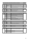
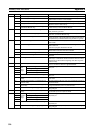
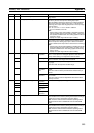
A524 00 to 15 Interrupt Counter 0 Counter PV These words contain the interrupt counter PVs for interrupt input
0 to 3 operating in counter mode.
The counter PV starts decrementing from the counter SV. When
the counter PV reaches the 0, the PV is automatically reset to the
SV.
Range: 0000 to FFFF
A525 00 to 15 Interrupt Counter 1 Counter PV
A526 00 to 15 Interrupt Counter 2 Counter PV
A527 00 to 15 Interrupt Counter 3 Counter PV
A530 00 DM Write Request Bit (Coordinator Module to
Motion Control Module)
DM data transfer is executed from the Coordinator Module to
Motion Control Module when this bit turns ON.
01 DM Read Request Bit (Motion Control Module to
Coordinator Module)
DM data transfer is executed from the Motion Control Module to
Coordinator Module when this bit turns ON.
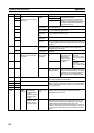
A531 00 to 15 Slot No. of Motion Control Module for DM Trans-
fer
Specifies the slot number (in 4-digit hexadecimal) for the Motion
Control Module with which DM data is to be transferred.
0001: Motion Control Module #1
0002: Motion Control Module #2
0003: Motion Control Module #3
0004: Motion Control Module #4
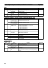
A532 00 to 15 DM Transfer Size (number of words) Specifies the size, in number of words, of the DM data to be trans-
ferred.
0001 to 01F3 hex (1 to 499 words)
A533 00 to 15 First DM Transfer Source Word Specifies the first address of the DM transfer source in the Coor-
dinator Module or Motion Control Module.
0000 to 7FFF hex
A534 00 to 15 First DM Transfer Destination Word Specifies the first address of the DM transfer destination in the
Coordinator Module or Motion Control Module.
0000 to 7FFF hex
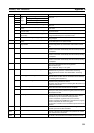
A535 14 Transfer Error Flag Turns ON when a DM data transfer error occurs.
15 Transfer Busy Flag Turns ON during DM data transfer and turns OFF when the trans-
fer has been completed.
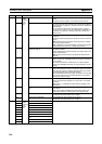
A550 00 to 15 Analog Input PV Contains the value input from the analog input port (using either
the END refresh or immediate refresh) in 4-digit hexadecimal.
The PV range depends on the input range:
• 0 to 10 V: FE70 to 20D0 hex
• 0 to 5 V or 1 to 5 V: FF38 to 1068 hex
•
−10 to 10 V: DDA0 to 2260 hex
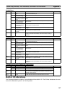
A552 00 Analog Input Status User Adjustment
Completed
OFF: Not adjusted
ON: Adjustment completed
07 Analog Sampling
Started
OFF: Not started
ON: Started
08 Factory Adjustment
Data Error
OFF: No Error
ON: Error (Checked at power ON.)
09 User Adjustment
Data Error
OFF: No Error
ON: Error (Checked at power ON.)
15 Analog Sampling
Overlap
OFF: Normal sampling
ON: The next sampling operation occurred
before the present sampling operation com-
pleted.
Address Bits Name Function