


354
Auxiliary Area Allocations Appendix D
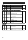
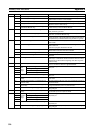
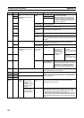
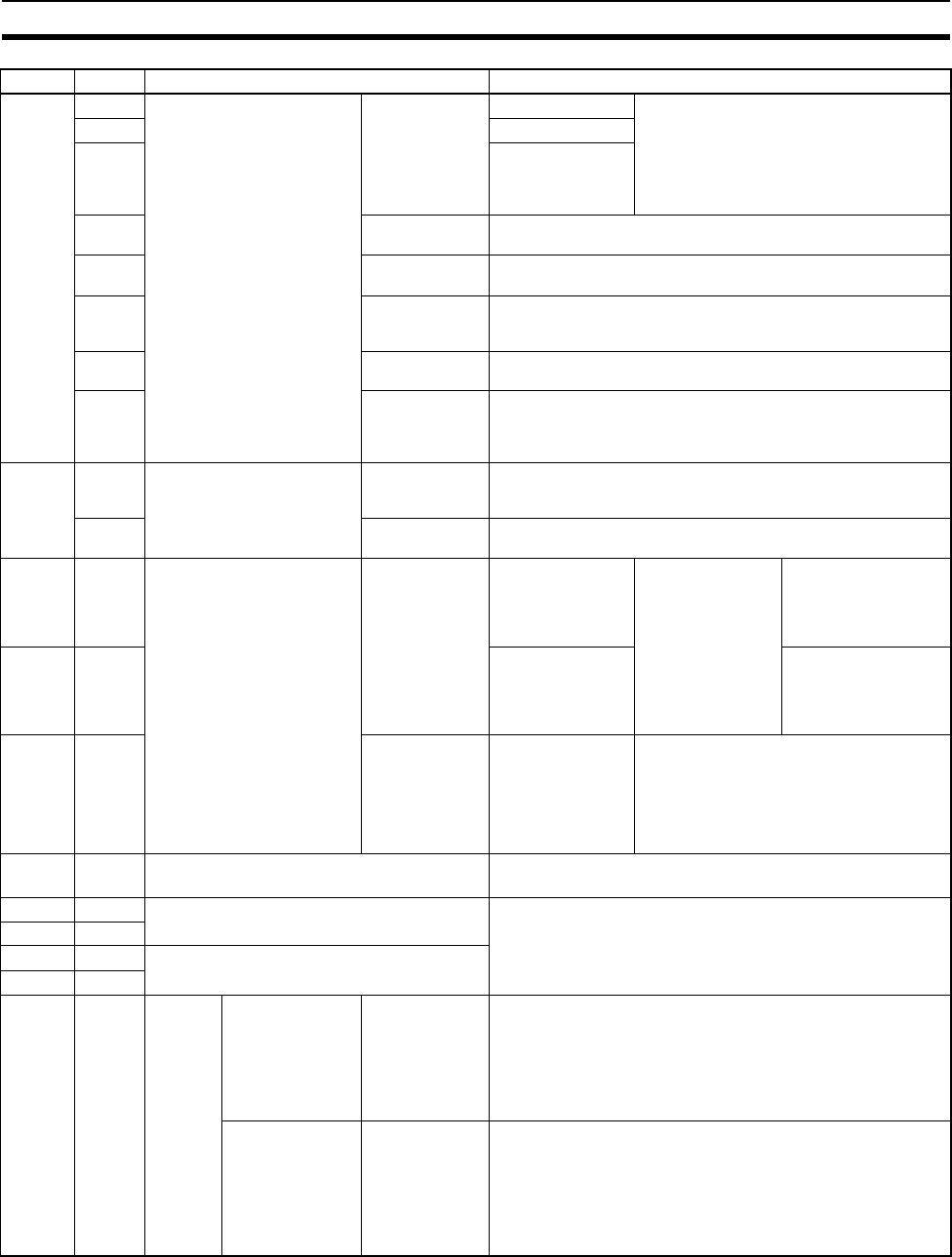
A570 00 Adjustment Mode Command
Bits
(Effective only when A575 is
5A5A hex.)
Adjustment
Enable
Analog Input OFF: Adjustment disabled.
ON: Adjustment enabled.
When one of these bits is turned ON, the
default value (offset or gain value) corre-
sponding to the selected I/O signal range is
transferred to Adjustment Mode Monitor
Area (A572 and A573).
02 Analog Output 1
03 Analog Output 2
07 Adjustment
Mode Specifier
OFF: Offset adjustment
ON: Gain adjustment
12 Adjustment
Value Increment
While this bit is ON, the offset or gain value will be incremented
by one resolution unit each 0.5 ms.
13 Adjustment
Value Decre-
ment
While this bit is ON, the offset or gain value will be decremented
by one resolution unit each 0.5 ms.
14 Adjustment
Value Clear
OFF to ON: Clears the adjustment data to the factory defaults.
15 Adjustment
Value Set
OFF to ON: Reads the present value in the Adjustment Mode
Monitor Area (A572 and A573) and saves this value to flash mem-
ory. This adjustment value will be used for the next normal mode
operation.
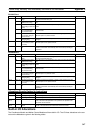
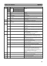
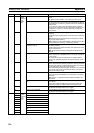
A571 00 Adjustment Mode Status Adjustment
Operation Error
ON when an operational error has been made, such as turning
ON both the Analog Input and Analog Output 2 Adjustment
Enable Bits at the same time.
15 Adjustment
Mode Started
ON during adjustment mode operation (when A575 contains
5A5A hex).
A572 00 to 15 Adjustment Mode Monitor
(Effective only when A575 is
5A5A hex.)
Both Analog
Input and Ana-
log Outputs
Setting Offset Mon-
itor
The values in these
words can be over-
written directly,
without using the
Adjustment Value
Increment/Decre-
ment Bits.
•
−10 to 10 V: FE0C to
01F4 hex
• 0 to 10 V, 0 to 5 V, 1
to 5 V: FF38 to 00C8
hex
A573 00 to 15 Gain Value Monitor •
−10 to 10 V: 1194 to
157C hex
• 0 to 10 V, 0 to 5 V, 1
to 5 V: 0ED8 to 1068
hex
A574 00 to 15 Analog Inputs Number of Average
Value Samples in
Adjustment Mode
Indicates the number of values to be aver-
aged to obtain the Offset/Gain Value Moni-
tor values in adjustment mode. The number
of samples can be set between 0000 and
0040 hex (0 to 64). Set this parameter
before turning ON the Adjustment Enable
Bit.
A575 00 to 15 Adjustment Mode Password 5A5A hex: Adjustment mode enabled.
Other value: Adjustment mode disabled.
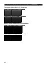
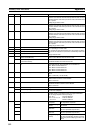
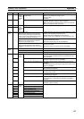
A600 00 to 15 High-speed Counter 1 PV Range: 8000 0000 to 7FFF FFFF
Note For a Linear Counter, high-speed counter overflows/under-
flows are checked when the PV is read (i.e., when Module inter-
nal I/O is refreshed).
A601 00 to 15
A602 00 to 15 High-speed Counter 2 PV
A603 00 to 15
A604 to
A605
00 to 15 High-
speed
Counter
1
For following
counter modes
• Absolute linear
(CW
−)
• Absolute circular
• Absolute linear
(CW+)
PV of absolute
number of rota-
tions
Contains the number of rotations data (PV) read from the
Encoder when the SEN signal is input to the Servo Driver.
8000 0000 to 7FFF FFFF hex
For following
counter modes
• Linear counter
• Circular counter
Monitor data • When monitoring counter movements (mode 1), contains the
absolute value of the amount of change in the PV of the high-
speed counter over the specified sampling time as a 8-digit
hexadecimal value (0000 0000 to FFFF FFFF hex).
• When monitoring the counter frequency (mode 2), contains the
frequency of the high-speed counter calculated from the PV of
the high-speed counter between 0 and 7A120 hex (0 and 500
kHz).
Address Bits Name Function