


161
Pulse Inputs Section 7-5
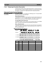
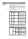
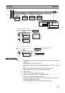
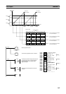
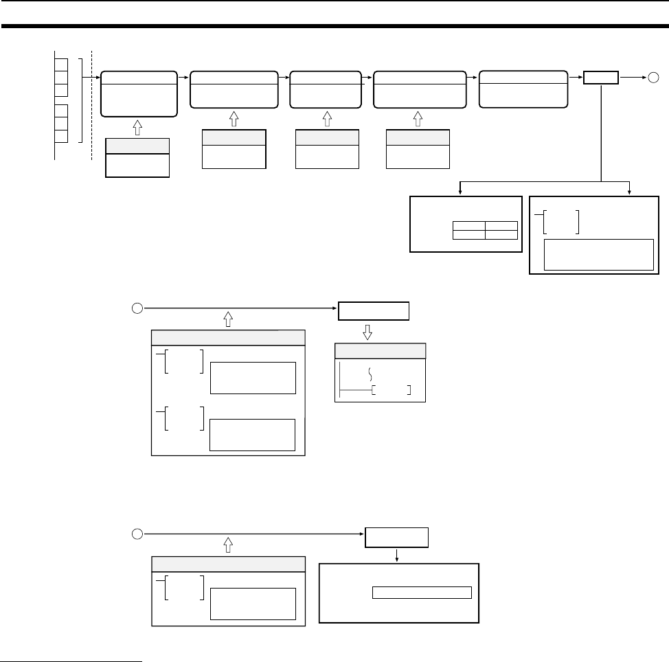
Mode 1 Procedure
1,2,3... 1. Determine the Counting Speed, Input Mode, Reset Method, and Counter
Operation.
• Counting Speed: 50 kHz or 500 kHz
• Input Mode: Phase Differential, Increment/Decrement, or Pulse + Direc-
tion
• Reset method: Phase Z and software reset, or Software reset
• Counter Operation: Circular Counter or Linear Counter
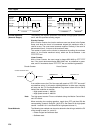
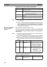
2. Wire the input.
3. Make the necessary System Setup settings.
• Counter Data Display: Counter movements (mode 1)
4. Create the necessary ladder programming.
• Turn ON the High-speed Counter 1 or 2 Start Bit (A610.00 or A611.00)
and start the high-speed counter.
• Turn ON the Measurement Start Bit (A610.02 or A611.02).
A601 A600
A603 A602
Pulse input 1
A
B
Z
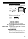
PRV HIGH-SPEED
COUNTER PV READ
Read PV.
Count
Refresh PV (once each cycle).
Counter PV
Reset Method
Phase-Z /software reset
Software reset
Refresh PV (immediate refresh).
Pulse input 2
A
B
Z
Port 1
Port 2
(Auxiliary Area)
A
Counter Operation
Circular Counter
Linear Counter
Input Mode
System Setup
Input
Reset Counter Operation
Counting Speed
Phase differential
Pulse + Direction
Increment/Decrement
System Setup System Setup
Counting Speed
50 kHz
500 kHz
System Setup
Only when using high-speed
counter interrupts.
Counter Start Bit
Turn ON A610.00 or
A611.00.
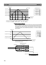
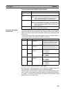
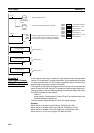
CTBL COMPARISON TABLE LOAD
Register table only.
Register table and
start comparison.
INI MODE CONTROL
Change PV.
Start/Stop comparison.
Ladder Program
A
Interrupt generated.
Specified Interrupt Task
END
See note.
Target-value comparison interrupt
Check count
(compare).
A
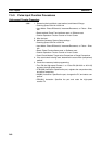
Pattern storage
A613 or A615
15 0
Range Comparison, Bit Pattern Output
CTBL COMPARISON TABLE LOAD
Perform comparison.
Ladder Program
Range comparison is performed only when
the instruction is executed.
Note: