


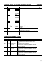

351
Auxiliary Area Allocations Appendix D
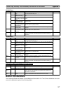
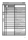
A414 02 RS-422A
Port
Error
Flags
Parity Error Flag These error flags turn ON when an error has occurred at the RS-
422A port.
03 Framing Error Flag
04 Overrun Error Flag
05 Timeout Error Flag
08 RS-422A Port Communications Error Flag Turns ON when a communications error has occurred at the RS-
422A port.
09 RS-422A Port Send Ready Flag (no-protocol
mode)
Turns ON when the RS-422A port is ready to send data in no-pro-
tocol mode.
10 RS-422A Port Reception Completed Flag (no-
protocol mode)
Turns ON when the RS-422A port has completed the reception in
no-protocol mode.
11 RS-422A Port Reception Overflow Flag (no-pro-
tocol mode)
Turns ON when a data overflow occurred during reception
through the RS-422A port in no-protocol mode.
15 RS-422A Port Settings Changing Flag Turns ON while the RS-422A port’s communications settings are
being changed.
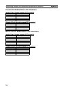
A415 00 to 15 RS-422A Port Reception Counter (no-protocol
mode)
Indicates (in binary) the number of bytes of data received when
the RS-422A port is in no-protocol mode.
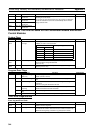
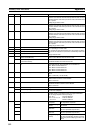
A500 14 Error Log Pointer Reset and Memory Not Held
Flag OFF Bit
The error log pointer in A408 is reset to 0000 hex and Memory
Not Held Flag (A404.14) is turned OFF when this bit is turned
ON.
A502 00 RS-232C Port Restart Bit Turn this bit ON to restart the RS-232C port.
This bit is turned OFF automatically when the restart processing
is completed.
01 Peripheral Port Restart Bit Turn this bit ON to restart the peripheral port.
This bit is turned OFF automatically when the restart processing
is completed.
02 RS-422A Port Restart Bit Turn this bit ON to restart the RS-422A port.
This bit is turned OFF automatically when the restart processing
is completed.
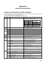
A507 00 to 15 Data Trace Period Data will be traced using the period specified here when tracing
each cycle is specified from the CX-Programmer.
0000 hex: Each cycle
0001 to 000F hex: Every 2 to 16 cycles
A508 09 Differentiate Monitor Completed Flag Turns ON when the differentiate monitor condition has been
established during execution of differentiation monitoring.
(This flag will be turned OFF when differentiation monitoring
starts.)
11 Trace Trigger Monitor Flag Turns ON when a trigger condition is established by the Trace
Start Bit (A508.14). OFF when the next Data Trace is started by
the Sampling Start bit (A508.15).
12 Trace Completed Flag Turns ON when sampling of a region of trace memory has been
completed during execution of a Trace.
Turns OFF when the next time the Sampling Start Bit (A508.15) is
turned from OFF to ON.
13 Trace Busy Flag Turns ON when the Sampling Start Bit (A508.15) is turned from
OFF to ON. Turns OFF when the trace is completed.
14 Trace Start Bit Turn this bit ON to establish the trigger condition. The offset indi-
cated by the delay value (positive or negative) determines which
data samples are valid.
15 Sampling Start Bit When a data trace is started by turning this bit from OFF to ON
from the CX-Programmer, the FQM1 will begin storing data in
Trace Memory by one of the three following methods:
1)Data is sampled at regular intervals (10 to 2,550 ms).
2)Data is sampled when TRSM(045) is executed in the program.
3)Data is sampled at the end of every cycle.
The operation of A508.15 can be controlled only from the CX-Pro-
grammer.
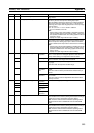
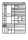
A509 15 Constant Cycle Time Exceeded Error Clear Bit Used to enable the constant cycle time function again after the
constant cycle time has been exceeded.
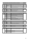
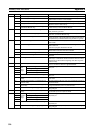
A510 to
A514
00 to 15 Macro Area Input Words Before the subroutine specified in MCRO(099) is executed, the
contents of the five words specified in the operand to be passed
to the subroutine are stored here.
A515 to
A519
00 to 15 Macro Area Output Words After the subroutine specified in MCRO(099) has been executed,
the results of the subroutine are transferred to these five words.
Address Bits Name Function