


93
Coordinator Module Section 4-1
System Setup The System Setup contains software switches used to make initial settings
and other settings. As shown in Appendix C System Setup, Auxiliary Area
Allocations, and Built-in I/O Allocations, addresses (words and bits) are allo-
cated for settings in the System Setup. The addresses can normally be
ignored when making the settings, however, because the settings follow CX-
Programmer menus.
Flash Memory When the user writes to the Coordinator Module, the user program, System
Setup settings, other parameters, and part of the DM Area are automatically
backed up to flash memory.
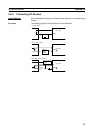
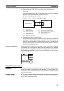
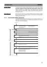
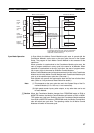
4-1-2 Coordinator Module Operation
The following flowchart shows the operation of the Coordinator Module. Pro-
gramming is executed before I/O is refreshed and peripherals are serviced.
This cycle is executed repeatedly.
Power ON
Startup
initialization
• Initialize hardware memory
and system work area.
• Detect connected Motion
Control Modules.
• Clear I/O memory.
• Check user memory.
• Clear forced status, etc.
Common
processing
• Read DIP switch settings. • Check I/O bus.
• Check user program memory.
Program
execution
• Operation processing: Execute the user programming.
• Error processing: Turn OFF outputs.
• After error: Clear I/O memory (unless a FALS instruction caused
the error.)
I/O
refreshing
Refresh built-in I/O.
Cyclic
refreshing
(See note.)
Exchange cyclic data with Motion Control Modules. (Refreshing is
stopped if there is a bus error.)
Note: Cyclic refreshing occurs in PROGRAM mode as well.
Peripheral
servicing
Perform the following servicing if any events have occurred.
• Motion Control Module event servicing
• Peripheral port servicing
• RS-232C port servicing
• RS-422A port servicing
Cycle
time