


358
Auxiliary Area Allocations Appendix D
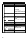
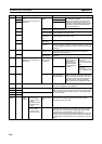
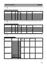
A626 00 Pulse
Output 1
Com-
mand
Bits
PV Reset Bit OFF: Pulse output 1 PV not reset.
ON: Resets pulse output 1 PV.
01 Range Comparison Results Clear Bit OFF: Does not clear the execution results (A630) or output bit
pattern (A631) from CTBL(882) execution for range comparison
for the pulse output PV.
ON: Clears the execution results (A630) or output bit pattern
(A631) from CTBL(882) execution for range comparison for the
pulse output PV.
A627 00 Pulse
Output 2
Com-
mand
Bits
PV Reset Bit Same as for Pulse Output 1 Command Bits.
01 Range Comparison Results Clear Bit
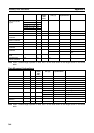
A628 07 Pulse
Output
Control
Bits
(Apply to
both
pulse
outputs 1
and 2.)
Speed Change Cycle Bit OFF: Sets the speed change cycle to 2 ms during pulse output to
ACC(888) or PLS2(887).
ON: Sets the speed change cycle to 1 ms during pulse output to
ACC(888) or PLS2(887).
14 PLS2 Pulse Output Direction Priority
Mode Bit
OFF: Sets Direction Priority Mode.
In Direction Priority Mode, pulses are output only when the pulse
output direction and the direction of the specified absolute posi-
tion are the same.
ON: Sets Absolute Position Priority Mode.
In Absolute Position Priority Mode, pulses are always output in
the direction of the specified absolute position.
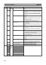
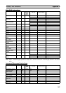
A630 00 to 15 Pulse
Output 1
Monitor
Data
Range Comparison Results Contains the CTBL(882) execution results for range comparison.
Bits 00 to 15 correspond to ranges 1 to 16.
OFF: No match
ON: Match
A631 00 to 15 Output Bit Pattern Contains the output bit pattern when a match is found for
CTBL(882) execution results for range comparison
Note If more than one match is found, an OR of the output bit
patterns with matches will be stored here.
A632 00 to 15 Pulse
Output 2
Monitor
Data
Range Comparison Results Same as for Pulse Output 1 Monitor Data.
A633 00 to 15 Output Bit Pattern
Address Bits Name Function