47
Memory Block Diagram Section 2-7
2-7 Memory Block Diagram
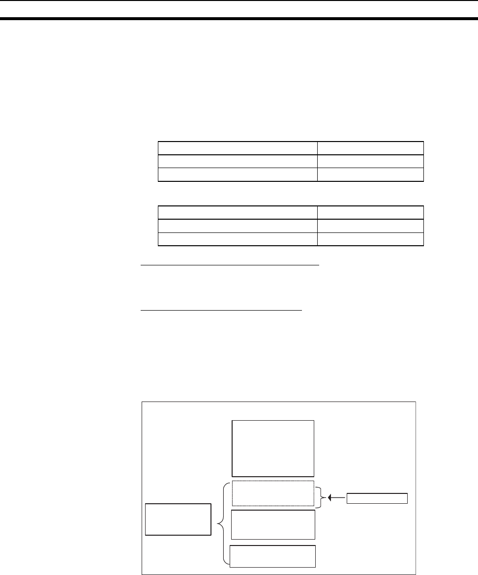
Coordinator Module and Motion Control Module memory has the following
block configurations.
• I/O Memory Area: Memory accessible from user programs.
• User Memory (UM): User programs and parameter area (See note 1.)
The following tables show the backup methods for these memory areas.
• Coordinator Modules
• Motion Control Modules
Areas Backed Up by
Super Capacitors
Data backed up by super capacitors is lost if the super capacitor voltage
drops.
Areas Backed Up to Flash Memory
Data backed up to flash memory is not lost if the super capacity voltage drops.
Data transferred from the CX-Programmer or edited online and written to the
user program or parameters in the user memory is automatically backed up to
flash memory. This means that user memory data (both user program and
parameter area data) is not lost if the super capacitor voltage drops.
Coordinator Module/Motion Control Module
Note (1) The parameter area stores the Coordinator Module system information,
such as the System Setup.
(2) Data transferred to the Coordinator Module, e.g., from the CX-Program-
mer, is saved to flash memory. Motion Control Module data is backed up
only by the super capacitor.
Area Backup method
User memory Flash memory
I/O memory area (part of DM Area) Flash memory
Area Backup method
User memory Flash memory
I/O memory area (part of DM Area) Super capacitor
Internal RAM
I/O Memory Area
I/O bit area
Work bit areas
Cyclic refresh bit area
Sync data link bit area
Flash memory
Super capacitor
DM Area
D30000 to D32767
(See note 2.)
User Program
Parameter Area
(See note 1.)
Backup


