


356
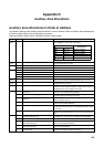
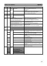
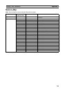
Auxiliary Area Allocations Appendix D
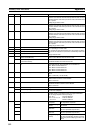
A610 00 High-
speed
counter 1
com-
mand
bits
Start Bit OFF: Stops counter operation. The counter PV will be main-
tained.
ON: Starts counter operation. The counter PV will be reset.
01 Reset Bit OFF: If a software reset is set in the System Setup, the counter
PV will not be reset when internal I/O is refreshed in the Motion
Control Module. If a phase Z + software reset is set, disables the
phase Z input.
ON: If a software reset is set in the System Setup, resets the
counter PV to 0 when internal I/O is refreshed in the Motion Con-
trol Module. If a phase Z + software reset is set, enables the
phase Z input.
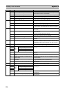
02 Measurement Start Bit OFF: Disables measuring changes in counter PV or the counter
frequency.
ON: Starts measuring changes in counter PV or the counter fre-
quency.
Note Measuring the high-speed counter frequency is possible
only for high-speed counter 1.
Note Valid when Counter Data Display in System Setup is set to
Counter Movements (mode 1) or Frequency (mode 2).
03 Measurement Direction Bit (mea-
surement mode 2)
OFF: Forward (up)
ON: Reverse (down)
This bit specifies the up/down direction of the pulse input for fre-
quency measurement.
Note Always set this bit before turning ON the Measurement
Start Bit.
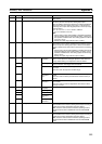
04 Range Comparison Results Clear Bit OFF: Does not clear the execution results (A612) or output bit
pattern (A613) from CTBL(882) execution for range comparison
for the counter.
ON: Clears the execution results (A612) or output bit pattern
(A613) from CTBL(882) execution for range comparison for the
counter.
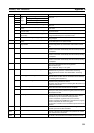
05 Absolute Offset Preset Bit OFF: Does not preset the offset.
OFF to ON: Stores the number of multi-turns read from the Servo
Driver and the number of initial incremental pulses as an offset in
the Absolute Offset value in the System Setup.
When establishing the machine origin, the position from the abso-
lute encoder origin is set as the Absolute Offset in the System
Setup as the machine origin.
06 Absolute Present Value Preset Bit OFF: Disables the absolute present value preset.
OFF to ON: Stores the Absolute PV in the counter 1 PV (A600
and A601).
Note Refer to 7-7-6 Absolute Present Value for details on the
absolute PV.
07 Absolute Number of Rotations Read
Bit
OFF: Disables reading the number of rotations data from the
Servo Driver.
OFF to ON: Outputs the SEN output to the Servo Driver and
receives the number of rotations data on the phase A input.
08 Latch Input 1 Enable Bit OFF: Disables the external latch input 1 signal.
ON: Enables the external latch input 1 signal.
09 Latch Input 2 Enable Bit OFF: Disables the external latch input 2 signal.
ON: Enables the external latch input 2 signal.
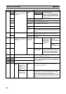
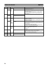
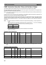
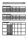
A611 00 High-
speed
counter 2
com-
mand
bits
Start Bit Same as command bits for high-speed counter 1.
01 Reset Bit
02 Measurement Start Bit
03 Reserved
04 Range Comparison Results Clear Bit
05 Absolute Offset Preset Bit
06 Absolute Present Value Preset Bit
07 Absolute Number of Rotations Read
Bit
08 Latch Input 1 Enable Bit
09 Latch Input 2 Enable Bit
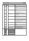
Address Bits Name Function