


349
Appendix D
Auxiliary Area Allocations
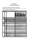
Auxiliary Area Allocations in Order of Address
The following table lists the Auxiliary Area allocations in order of address. Refer to Auxiliary Area Allocations by
Function on page 329 for a list of allocations by function.
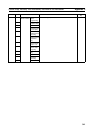
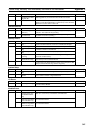
Read-only Words: A000 to A447, Read/Write Words: A448 to A649
Address Bits Name Function
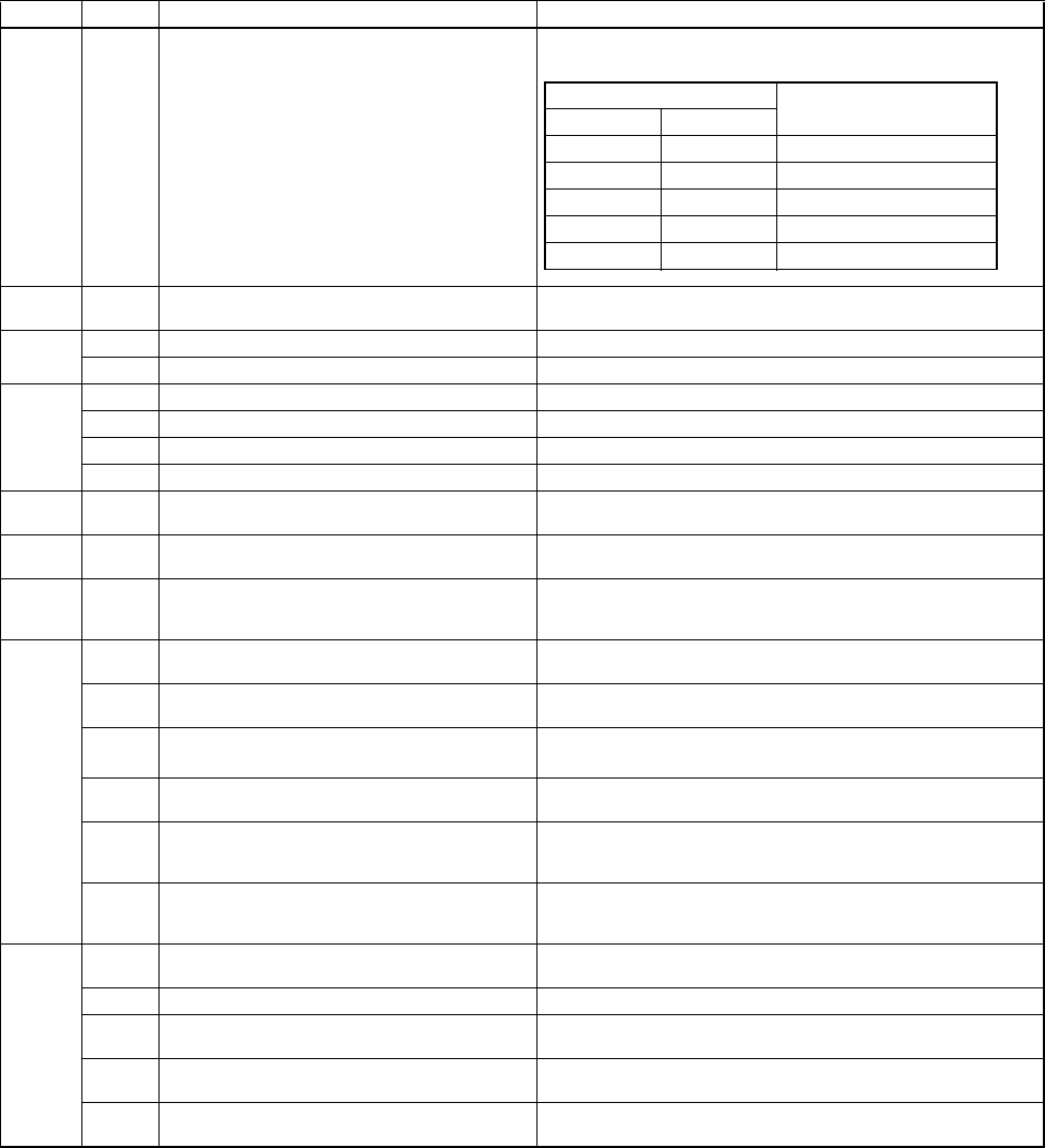
A000 to
A015
00 to 15 Subroutine Input Condition Flags These flags contain the status of the input condition for JSB(982)
when JSB(982) is used to call a subroutine.
A100 to
A199
00 to 15 Error Log Area When an error has occurred, the error code and error contents
are stored in the Error Log Area.
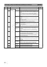
A200 11 First Cycle Flag ON for one cycle after FQM1 operation begins.
12 Step Flag ON for one cycle when step execution is started with STEP(008).
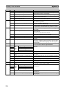
A202 00 Motion Control Module slot 1 ON if the Motion Control Module is in slot 1.
01 Motion Control Module slot 2 ON if the Motion Control Module is in slot 2.
02 Motion Control Module slot 3 ON if the Motion Control Module is in slot 3.
03 Motion Control Module slot 4 ON if the Motion Control Module is in slot 4.
A206 to
A207
00 to 15 Maximum Cycle Time These words store the maximum cycle time every cycle. The
cycle time is recorded in 8-digit hexadecimal (unit: 0.01 ms).
A208 to
A209
00 to 15 Present Cycle Time These words stores the present cycle time every cycle in 8-digit
hexadecimal (unit: 0.01 ms).
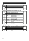
A400 00 to 15 Error code When a non-fatal error (user-defined FAL(006) or system error) or
a fatal error (user-defined FALS(007) or system error) occurs, the
hexadecimal error code is written to this word.
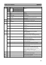
A401 06 FALS Error Flag
(fatal error)
Turns ON when a non-fatal error is generated by the FALS(006)
instruction. The FQM1 will stop operating.
08 Cycle Time Too Long Flag (fatal error) Turns ON if the cycle time exceeds the maximum cycle time set in
the System Setup (the Watch Cycle Time).
09 Program Error Flag
(fatal error)
ON when program contents are incorrect.
Module operation will stop.
10 I/O Setting Error Flag Turns ON when more than four Motion Control Modules are con-
nected to the Coordinator Module.
14 I/O Bus Error Flag Turns ON when an error occurs in transferring data between the
Coordinator Module and Motion Control Modules. Module opera-
tion will stop.
15 Memory Error Flag (fatal error) Turns ON when there is an error in the memory. FQM1 operation
will stop and the ERR indicators on the front of the Modules will
light.
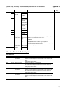
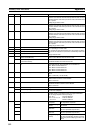
A402 05 Motion Control Module Monitoring Error Flag
(Coordinator Module only)
Turns ON in the Coordinator Module when a system error, such
as a WDT error, occurs in any of the Motion Control Modules.
10 System Setup Error Flag Turns ON when there is a setting error in the System Setup.
13 Coordinator Module WDT Error Flag (Motion
Control Modules only)
Turns ON in the Motion Control Modules when a WDT error
occurs in the Coordinator Module.
14 Coordinator Module Fatal Error Flag (Motion
Control Modules only)
Turns ON in the Motion Control Modules when a fatal error occurs
in the Coordinator Module.
15 FAL Error Flag
(non-fatal error)
Turns ON when a non-fatal error is generated by executing
FAL(006). The FQM1 will continue operating.
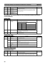
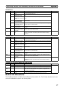
Address Corresponding
subroutines
Word Bits
A000 00 to 15 SBN000 to SBN015
A001 00 to 15 SBN016 to SBN031
A002 00 to 15 SBN032 to SBN047
to to to
A015 00 to 15 SBN240 to SBN255