


324
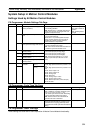
System Setup, Auxiliary Area Allocations, and Built-in I/O Allocations Appendix C
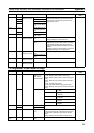
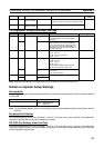
Note Always set the Circular Maximum Count when setting any of the circular operation modes.
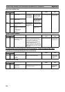
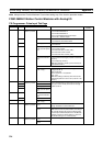
FQM1-MMA21 Motion Control Modules with Analog I/O
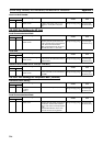
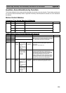
CX-Programmer: Pulse Input Tab Page
Address Bits Function Remarks When setting
is read
+320 00 to 03 High-speed
counter 1 (Counter
1)
Input method 0 hex: Phase differential x1
1 hex: Phase differential x2
2 hex: Phase differential x4
3 hex: Increment/decrement pulse inputs
4 hex: Pulse + direction inputs
At power ON
04 to 07 Reset method 0 hex: Software reset
1 hex: Phase Z and software reset
08 to 11 Counting speed 0 hex: 50 kHz
1 hex: 500 kHz
12 to 15 Counter operating
mode (Counter opera-
tion)
0 hex: Linear counter
1 hex: Circular counter
2 hex: Absolute linear counter (CW
−)
3 hex: Absolute circular counter
4 hex: Absolute linear counter (CW+)
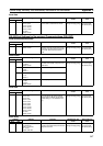
+321 00 to 03 Counter data to moni-
tor (Counter data dis-
play)
0 hex: Do not monitor (Non-monitor)
1 hex: Counter PV changes (Counter movements
(mode 1))
2 hex: Frequency (mode 2)
Note The frequency (mode 2) can be set only for
high-speed counter 1.
04 to 15 Reserved
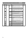
+322 00 to 15 Sampling time (for
mode 1 only)
Sets the sampling time for monitoring counter PV
changes (mode 1)
0000: Cycle time
0001 to 270F hex: 1 to 9,999 ms
(unit: 1 ms)
Note This setting is valid only when the Counter
Data Display (bits 00 to 03 of +321) is set to 1 hex
(mode 1).
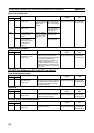
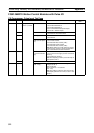
+323 00 to 03 High-speed
counter 2 (Counter
2)
Input method Same as for high-speed counter 1 except that fre-
quency measurement (Counter data to monitor, bit
00 to 03 of +324: 02 hex) cannot be set for high-
speed counter 2.
04 to 07 Reset method
08 to 11 Counting speed
12 to 15 Counter operating
mode (Counter opera-
tion)
+324 00 to 03 Counter data to moni-
tor (Counter data dis-
play)
04 to 15 Reserved
+325 00 to 15 Sampling time (for
mode 1 only)
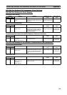
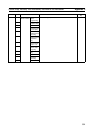
+326 to 327 00 to 15 High-speed
counter 1 (Counter
1)
Circular maximum
count
Sets the maximum circular counter value.
Range: 0000 0001 to FFFF FFFF hex
Absolute encoder res-
olution
0000 0001 to 0000 FFFF hex
Note Set this value in pulses/rotation according to
the encoder dividing ratio set for the Servo Driver
and the input method multiplier set for the Module.
Example: If the Servo Driver setting is 1,000 and
the Module setting is x4, set FA0 (4,000).
+328 to 329 00 to 15 High-speed
counter 2 (Counter
2)
Circular maximum
count
Same as for high-speed counter 1.
Absolute encoder res-
olution