


25
Function Tables Arranged by Purpose Section 1-7
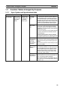
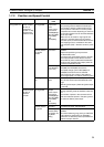
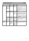
1-7-3 Measuring Input Pulses
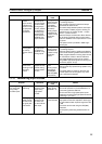
Speed control Torque control
(position +
torque control)
Individual axis
control for mold-
ing equipment
and similar
applications
Switching
between posi-
tion and torque
control modes.
During torque
control, perform-
ing speed con-
trol using high-
speed control
loops based on
feedback from
torque sensors.
• Analog input
• Pulse input (for
Servo Drivers
compatible
with Absolute
Encoders)
• Analog output
• Feedback cal-
culations using
ladder pro-
grams
7-9 Analog Input Functions
7-10 Analog Outputs
Uses 2 analog outputs for speed and torque
commands for Servo Driver.
Can switch freely between position and torque
control modes in ladder program, allowing for
operations such as position control → torque
control → position control.
Speed and torque commands to Servo Drivers
can be freely controlled during torque control
based on feedback from torque sensors via ana-
log inputs.
Fine speed control is possible in FQM1 high-
speed cycle.
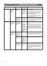
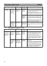
Line control
(winding/feed-
ing control)
Tension control,
etc.
Performing ana-
log output con-
trol based on
feedback using
analog inputs
• Analog input
• Analog output
• Feedback cal-
culations using
ladder pro-
grams
7-9 Analog Input Functions
7-10 Analog Outputs
Performs speed control of winding and feeding
motors while executing feedback calculations in
ladder programs based on analog input informa-
tion from dancer rollers or tension detectors.
High-speed feedback loops can be created
using FQM1 high-speed cycles and analog I/O
conversion (approx. 40 µs).
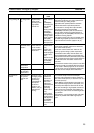
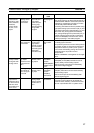
Simple speed
control corre-
sponding to time
axis using
inverter
Controlling
stepped or trap-
ezoidal analog
outputs based
on time
• Timer instruc-
tions
• Analog output
instructions
(SPED(885)
and ACC(888)
instructions)
7-10 Analog Outputs
Used to create any speed change pattern using
an inverter.
The speed pattern is based on the time axis,
and the speed can be changed to any value
once a set time has passed.
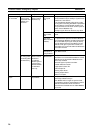
Purpose Operation Main functions
used
Details
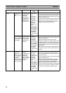
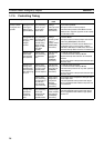
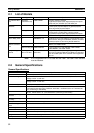
Detecting posi-
tion and length
using rotary
encoder inputs
High-precision
positioning
Counts high-
speed encoder
output using
high-speed
counter
Counting at
2MHz (phase
differential × 4)
7-5-8 Pulse Input Function Description
Set counter operation to phase differential × 4
and counting speed to 500 kHz.
Can be used when high-speed pulse inputs
need to be counted using high-speed counter for
positioning in µm-units.
Reading high-
speed counter
PV when mark
has gone past
mark sensor
Latching high-
speed counter
PV when sen-
sor turns ON for
latch input
High-speed
counter PV latch
7-5-8 Pulse Input Function Description
High-speed counter PV captured to latch regis-
ter when external latch inputs change from OFF
to ON.
The values can be read using the PRV(881)
instruction.
Can be quickly read using hardware latch cir-
cuits.
Purpose Operation Main functions
used
Details