


302
I/O Memory Appendix B
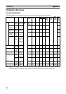
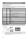
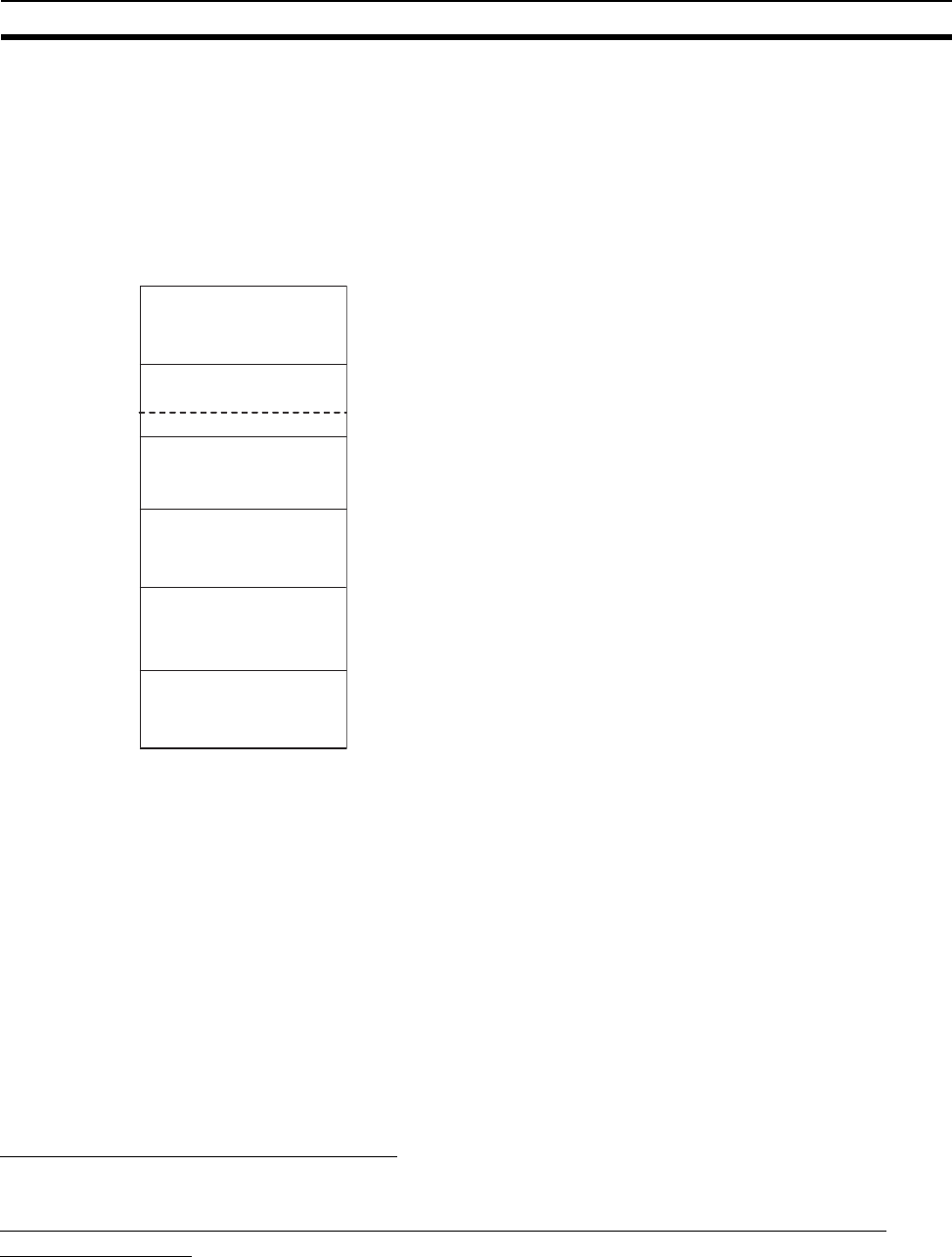
CIO Area
Overview
It is not necessary to input the “CIO” prefix when specifying an address in the CIO Area. The CIO Area is gen-
erally used for data exchanges, such as I/O refreshing between Modules (Coordinator Module and Motion
Control Modules). Words that are not allocated to Modules may be used as work words and work bits in the
program only.
Note The above figure depicts the CIO Area of the Coordinator Module. For the Motion Control Module, the
following area ranges are different.
• Serial PLC Link Bit Area: Not provided
• Cyclic Refresh Bit Area: CIO 0100 to CIO 0109
• Work Area: CIO 0002 to CIO 0099
CIO 0110 to CIO 0199
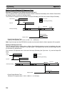
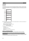
The CIO Area includes the following four areas.
• I/O Bit Area
• Cyclic Refresh Bit Area
• Synchronous Data Link Bit Area
•Work Areas
• Serial PLC Link Bit Areas (Coordinator Module only)
I/O Bit Area: CIO 0000 and CIO 0001
These words are allocated to built-in I/O terminals the Coordinator Module or Motion Control Module.
Cyclic Refresh Bit Area: CIO 0100 to CIO 0139 (CIO 0100 to CIO 0109 for Motion
Control Modules)
In the Coordinator Module, 10 words are refreshed every cycle for each Motion Control Module. These words
contain Motion Control Module status, general-purpose I/O, and other information. (Refreshing these words is
not necessarily synchronized with the Motion Control Module Cycles.)
15
0
CIO 0000
CIO 0001
(CIO 0002)
(CIO 0099)
CIO 0100
CIO 0140
(CIO 0139)
CIO 0200
CIO 0199
CIO 0220
CIO 0219
CIO 0255
(CIO 0080)
I/O Bit Area
Work Area
Serial PLC Link Bit Area
Cyclic Refresh Bit Area
Work Area
Synchronous Data
Link Bit Area
Work Area