


86
Wiring Precautions Section 3-6
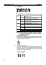
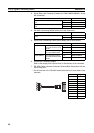
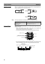
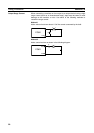
Inductive Loads When an inductive load is connected to I/O, connect a surge suppressor or
diode in parallel with the load as shown below.
Note Use surge suppressors and diodes with the following specifications.
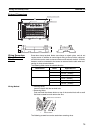
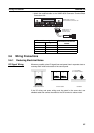
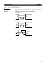
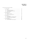
External Wiring Observe the following precautions for I/O wiring, power supply wiring, and
power line wiring.
• When multi-conductor signal cable is being used, do not combine I/O
wires and other control wires in the same cable.
• If wiring racks are parallel, allow at least 300 mm between the racks.
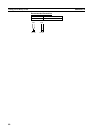
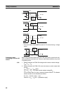
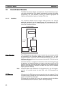
• If the I/O wiring and power cables must be placed in the same duct, they
must be shielded from each other using grounded steel sheet metal.
L
IN
COM
OUT
COM
OUT
COM
L
+
Diode
DC input
Relay output or
triac output
Surge suppressor
Relay output or
transistor output
Diode
Surge suppressor specifications Diode specifications
Resistor: 50 Ω
Capacitor: 0.47 µF
Voltage: 200 V
Breakdown voltage: 3 times load voltage min.
Mean rectification current: 1 A
FQM1 I/O wiring
FQM1 power supply and
general control circuit wiring
Power lines
Ground to 100 Ω or less
Low-current cables
Control cables
Control cables
300 mm min.
300 mm min.
FQM1 I/O wiring
FQM1 power
supply and general
control wiring
Power lines
Steel sheet metal
Ground to 100 Ω or less
200 mm min.