


166
Pulse Inputs Section 7-5
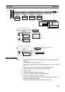
Example 3:
Latching High-speed
Counter PV
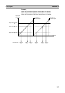
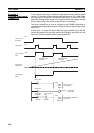
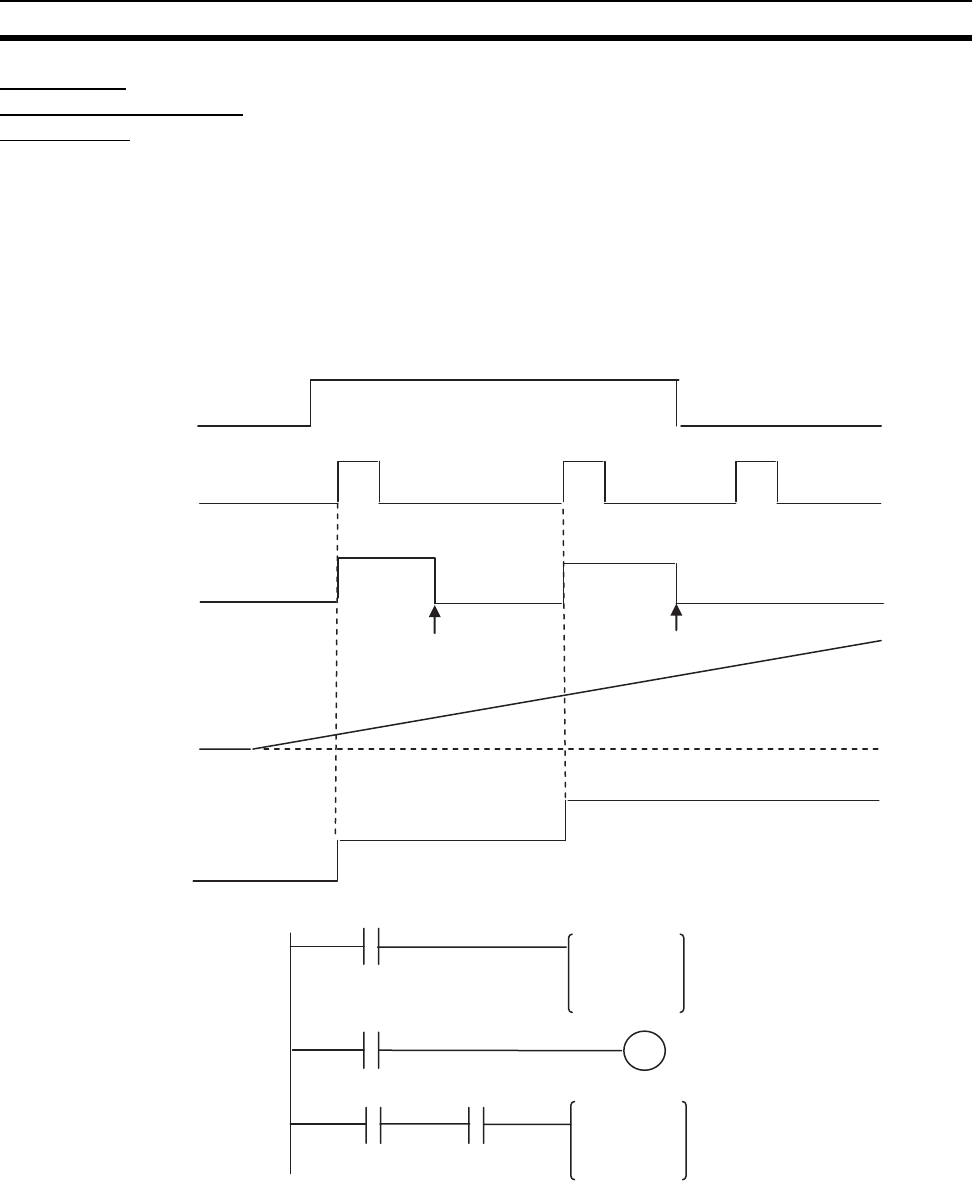
In this example, pulse input 1 operates a high-speed counter, the high-speed
counter PV is latched, and the captured high-speed counter PV is read. When
the Latch Input 1 Enable Bit is ON and the latch input 1 is turned OFF
→ON
externally, the high-speed counter PV is captured to the latch register and the
Count Latched Flag is turned ON during the next I/O refreshing.
The Count Latched Flag is used as a trigger for the PRV(881) instruction to
read the captured high-speed counter PV and the Count Latched Flag is then
turned OFF.
If latch input 1 is turned ON again while the Count Latched Flag is still ON
(before the captured PV has been read by the PRV(881) instruction), the old
captured PV will be refreshed with the new captured PV.
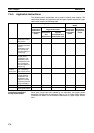
0
ON
OFF
OFF
ON
OFF
ON
Latch Input 1
Enable Bit
Latch input 1
High-speed
Counter PV
Latch register
value 1
PRV instruction
execution
PRV instruction
execution
Count Latched
Flag
A610.08
A608.08
A610.08
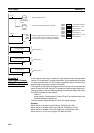
PRV
#0001
#0002
D00000
PRV
#0001
#0002
W000
Clear Latch
Start Latch
Latch Input 1
Enable Bit
Count Latched
Flag
Dummy read of
latch register
Read latched high-speed
counter PV.
Latch Input 1
Enable Bit