


14
Basic Operating Procedure Section 1-6
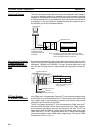
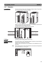
Wiring I/O terminals and connectors. Refer to 3-3 Wiring Module Connec-
tors for details.
3. Initial Hardware Settings
Set the DIP switch on the front of the Coordinator Module as required. Re-
fer to 2-3 Coordinator Module for details.
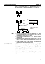
4. Turning ON Power and Checking Initial Operation
Connect the CX-Programmer (using CX-Programmer Ver. 5.0 with the
FQM1 Patch Software installed). Refer to 3-1-4 Connecting FQM1 Com-
ponents for details.
Check the power supply wiring and voltage and then turn ON the power
supply. Check the RDY indicator and CX-Prorammer display. Refer to 8-2
Connecting the CX-Programmer for details.
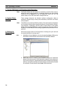
5. System Setup Settings Using the CX-Programmer
With the FQM1 in PROGRAM mode, change the settings in the System
Setup as necessary from the CX-Programmer online. (Another method is
to change the System Setup in CX-Programmer offline and transfer it to the
Coordinator Module and Motion Control Modules.) Set the Sync Mode un-
der Synchronization between Modules to ASync Mode to make debugging
easier. Refer to System Setup in the Coordinator Module on page 311 in
Appendix C System Setup, Auxiliary Area Allocations, and Built-in I/O Al-
locations for details.
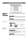
6. Writing the Programs
Write the programs for the Coordinator Module and Motion Control Mod-
ules with the CX-Programmer. Refer to Appendix A Programming and to
the FQM1 Instructions Reference Manual (Cat. No. O011) for details.
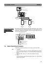
7. Transferring the Programs
Transfer the programs from CX-Programmer to the Coordinator Module
and Motion Control Modules.
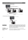
8. Testing Operation
a. Checking I/O Wiring
b. Trial Operation
Test operation after switching the FQM1 to MONITOR mode.
c. Monitoring and Debugging
Monitor operation from the CX-Programmer. Use functions such as
force-setting/force-resetting bits, tracing, and online editing to debug
the program.
Note If the Coordinator and Motion Control Modules are connected at
the same time, set the baud rate to 38.4 kpps max.
9. Saving and Printing the Programs
Save the debugged ladder programs and System Setup.
10. Running the Programs
Switch the FQM1 to RUN mode to run the programs.
Output wiring With the FQM1 in PROGRAM mode, force-set output bits
and check the status of the corresponding outputs.
Input wiring Activate sensors and switches and either check the status
of the input indicators or check the status of the corre-
sponding input bits with the CX-Programmer’s Bit/Word
Monitor operation.