


65
Wiring Section 3-2
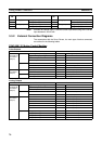
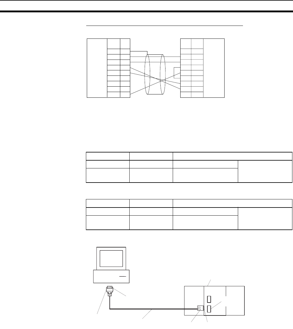
Peripheral Bus (Toolbus) Serial Communications Mode
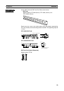
Use the following connectors and cables if making the RS-232C cable for RS-
232C port connections.
Applicable Connectors
■ Coordinator Module Connector
■ IBM PC/AT or Compatible Connector (9-pin, Male)
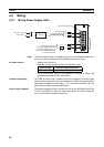
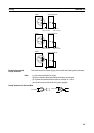
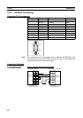
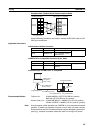
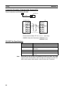
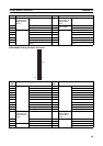
■ Connecting to an IBM PC/AT or Compatible
Recommended Cables Fujikura Ltd.: UL2464 AWG28
× 5P IFS-RVV-SB (UL product)
AWG 28
× 5P IFVV-SB (non-UL product)
Hitachi Cable, Ltd.: UL2464-SB (MA) 5P
× 28AWG (7/0.127) (UL product)
CO-MA-VV-SB 5P
× 28AWG (7/0.127) (non-UL product)
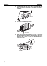
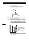
Note Use the special cables provided from OMRON for all connections whenever
possible. If cables are produced in-house, be sure they are wired correctly.
External devices and the Coordinator Module may be damaged if general-pur-
pose (e.g., computer to modem) cables are used or if wiring is not correct.
1
2
3
4
5
6
7
8
9
CD
RD
SD
ER
SG
DR
RS
CS
CI
Coordinator Module
1
2
3
4
5
6
7
8
9
FG
SD
RD
RS
CS
5V
DR
ER
SG
IBM PC/AT or compatible
RS-232C
interface
Signal
Signall
RS-232C
interface
9-pin D-sub
connector (male)
9-pin D-sub
connector (female)
Pin
No.
Pin
No.
Item Model Specifications
Plug XM2A-0901 9-pin male Used together
Hood XM2S-0911-E 9-pin, millimeter screws,
static resistant
Item Model Specifications
Plug XM2D-0901 9-pin female Used together
Hood XM2S-0913 9-pin, inch screws, static
resistant
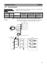
IBM PC/AT or
compatible
(9-pin, male)
Plug: XM2D-0901
(9-pin, female)
Hood: XM2S-0913
Recommended cable
Coordinator Module
RS-232C
port
Hood: XM2S-0911-E Plu
g
: XM2A-0901