


350
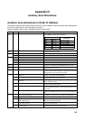
Auxiliary Area Allocations Appendix D
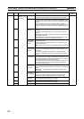
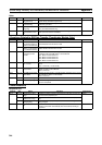
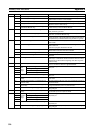
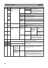
A403 00 UM Error Flag Turns ON when there is an error in the user memory.
04 System Setup Error Flag Turns ON when there is an error in the System Setup in the Coor-
dinator Module or Motion Control Module.
10 Flash Memory Error Flag Turns ON when the flash memory is physically destroyed.
13 Analog Offset/Gain Error Flag Turns ON when there is an error in the analog I/O offset/gain
adjustment value in flash memory.
14 Flash Memory DM Checksum Error Flag
(Coordinator Module only)
Turns ON when there is an error in the DM Area data backed up
in flash memory in the Coordinator Module.
A404 05 Constant Cycle Time Exceeded Flag Turns ON when the actual cycle time exceeds the specified con-
stant (minimum) cycle time.
06 Sync Cycle Time Too Long Flag Turns ON when one of the Modules exceeds the specified sync
cycle time. (Coordinator Module only)
14 Memory Not Held Flag Turns ON when corruption is found in the check performed after
turning ON power in the areas backed up during power interrup-
tions (DM Area (Coordinator Module only) and Error Log Area).
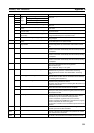
A405 11 No END Error Flag ON when there isn’t an END(001) instruction in each program
within a task.
12 Task Error Flag ON when a task error has occurred. The following conditions gen-
erate a task error.
There isn’t a program allocated to the task.
13 Differentiation Overflow Error Flag The allowed value for Differentiation Flags which correspond to
differentiation instructions has been exceeded.
14 Illegal Instruction Error Flag ON when a program that cannot be executed has been stored.
15 UM Overflow Error Flag ON when the last address in UM (User Memory) has been
exceeded.
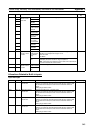
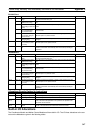
A408 00 to 15 Error Log Pointer When an error occurs, the Error Log Pointer (binary) is incre-
mented by 1 to indicate the location where the next error will be
recorded as an offset from the beginning of the Error Log Area
(A100 to A199).
A409 00 to 15 System Setup Error Location When there is a setting error in the System Setup, the location of
that error is written to A409 in 4-digit hexadecimal.
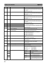
A410 02 RS-232C
Port
Error
Flags
Parity Error Flag These error flags turn ON when an error has occurred at the RS-
232C port.
03 Framing Error Flag
04 Overrun Error Flag
05 Timeout Error Flag
08 RS-232C Port Communications Error Flag Turns ON when a communications error has occurred at the RS-
232C port.
09 RS-232C Port Send Ready Flag (no-protocol
mode)
Turns ON when the RS-232C port is ready to send data in no-pro-
tocol mode.
10 RS-232C Port Reception Completed Flag (no-
protocol mode)
Turns ON when the RS-232C port has completed the reception in
no-protocol mode.
11 RS-232C Port Reception Overflow Flag (no-pro-
tocol mode)
Turns ON when a data overflow occurred during reception
through the RS-232C port in no-protocol mode.
15 RS-232C Port Settings Changing Flag Turns ON while the RS-232C port’s communications settings are
being changed.
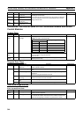
A411 00 to 15 RS-232C Port Reception Counter (no-protocol
mode)
Indicates (in binary) the number of bytes of data received when
the RS-232C port is in no-protocol mode.
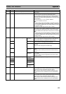
A412 02 Periph-
eral Port
Error
Flags
Parity Error Flag These error flags turn ON when an error has occurred at the
peripheral port.
03 Framing Error Flag
04 Overrun Error Flag
05 Timeout Error Flag
08 Peripheral Port Communications Error Flag Turns ON when a communications error has occurred at the
peripheral port.
15 Peripheral Port Settings Changing Flag Turns ON while the peripheral port’s communications settings are
being changed.
Address Bits Name Function