


111
Synchronous Data Refresh Section 5-4
Note (1) Addresses are the same for the Coordinator Module and all Motion Con-
trol Modules.
(2) When the synchronous data is one-word data (analog input values, ana-
log output values, built-in I/O, etc.), the other word can be used for gen-
eral-purpose data.
5-4-4 Settings
The following settings must be made beforehand when using the synchronous
data refresh function.
System Setup
(Coordinator Module)
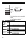
Synchronization between Modules and Sync Cycle Time must be set in the
Coordinator Module's System Setup.
Synchronization between Modules
Sync Cycle Time
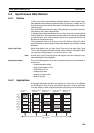
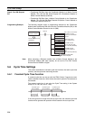
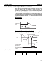
When the Sync Cycle Time is specified, all Motion Control Modules will syn-
chronize with the Coordinator Module cycle time in PROGRAM mode. The
specified Sync Cycle Time is enabled in RUN and MONITOR modes, and the
Motion Control Module cycle times will change to the set Sync Cycle Time
when in these modes.
Synchronous data link bits will be broadcast from each Module at the time
specified under Sync Cycle Time.
If an interrupt task 000 is created, it can be used as a regular interrupt task
executed each Sync Cycle Time.
When the Sync Cycle Time is on the default setting, the synchronous data link
bits are broadcast from each Module each Coordinator Module cycle. The
Motion Control Module cycles are synchronous with the Coordinator Module
cycle.
Note If the Sync Cycle Time Too Long Flag (A404.06) turns ON in the Coordinator
Module, it means that the Motion Control Module cycle time is longer than the
Sync Cycle Time. Either change the Sync Cycle Time or check the Motion
Control Module ladder program and shorten the Motion Control Module cycle
time to less than the Sync Cycle Time.
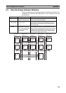
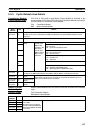
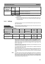
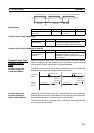
Sent from Motion
Control Module #4
CIO 0216 00 to 15 Set using upper 2 words of Select Synchronous Data in the System
Setup for Motion Control Module #4.
CIO 0217 00 to 15
CIO 0218 00 to 15 Set using lower 2 words of Select Synchronous Data in the System
Setup for Motion Control Module #4.
CIO 0219 00 to 15
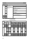
Synchronous Data
Link Bit Areas in
Coordinator and
Motion Control
Modules
Word
address
(See note
1.)
Bits Method for selecting type of synchronous data
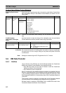
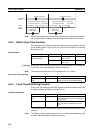
Name Settings Default Description Auxiliary Area
Flags
Enabled
Module Settings Tab Page
Sync Mode
Sync/Async Sync Synchronization
between Modules
--- At power ON
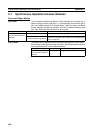
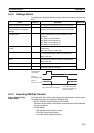
Name Settings Default Description Auxiliary Area
Flags
Enabled
Module Settings Tab Page
Sync Cycle Time
Default (cycle time)
(0.1 to 10.0 ms)
CM cycle time Sync cycle time
(unit: 0.1 ms)
A404.06
Sync Cycle Time
Too Long Flag
At power ON