


353
Auxiliary Area Allocations Appendix D
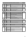
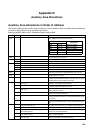
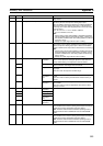
A559 00 to 15 Number of Analog Samples Indicates the number of data samples actually input since sam-
pling started.
A560 00 to 15 Analog Output 1 Output Value When an END refresh is selected, the 4-digit hexadecimal value
set here by the user is output from analog output port 1.
When immediate refreshing is selected, the 4-digit hexadecimal
value being output from analog output port 1 is stored here for
monitoring. The output value range depends on the output range,
as shown below.
• 0 to 10 V, 0 to 5 V or 1 to 5 V: FF38 to 1068 hex
•
−10 to 10 V: EA84 to 157C hex
Note
1. Set the analog output method (END or immediate refreshing)
with the System Setup’s output method setting. A setting of 0
hex specifies an END refresh. This setting applies to both ana-
log output 1 and 2.
2. Specify the output range with the output 1 setting.
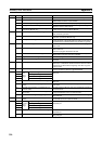
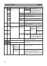
A561 00 to 15 Analog Output 2 Output Value This word has the same settings as the analog output 1 output
value (A560), above. (When an END refresh is selected, set the
value to output from analog output port 2. When an immediate
refresh is selected, the output value is stored here for monitoring.)
Note
1. Set the analog output method (END or immediate refresh) with
the System Setup’s output method setting. A setting of 0 hex
specifies an END refresh. This setting applies to both analog
output 1 and 2.
2. Specify the output range with the output 2 setting.
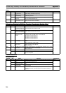
A562 00 Analog Output 1 Flags User Adjustment
Completed
Initial value is 0.
Set to 1 if user performs offset/gain adjustment and Returns to
factory default setting of 0 if adjustment value is cleared.
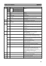
04 Operating ON: ON while the analog output is being changed by ACC(888).
OFF: Turned OFF when target value is reached.
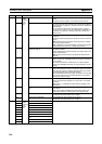
08 Output SV Error ON: ON when the output SV setting is outside of the allowed set-
ting range.
OFF: OFF when the output SV is within range.
12 Factory Adjust-
ment Value
Error
ON: ON when the factory-set data stored in flash memory is
invalid.
OFF: OFF when the factory-set data stored in flash memory is
normal.
14 User Adjustment
Value Error
ON: ON when the user-set adjustment value stored in flash mem-
ory is invalid.
OFF: OFF when the user-set adjustment value stored in flash
memory is normal.
A563 00 Analog Output 2 Flags User Adjustment
Completed
Same as for Analog Output 1 Flags.
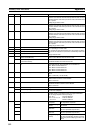
04 Operating
08 Output SV Error
12 Factory Adjust-
ment Value
Error
14 User Adjustment
Value Error
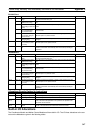
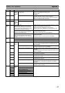
A564 00 Analog Output 1 Conversion Enable Bit ON: Enables D/A conversion (enables analog output).
OFF: Disables D/A conversion (analog values output according to
Output Stop Function specification in System Setup).
Note This bit is cleared when the Modules operating mode is
changed between RUN or MONITOR mode and PROGRAM
mode.
A565 00 Analog Output 2 Conversion Enable Bit ON: Enables D/A conversion (enables analog output).
OFF: Disables D/A conversion (analog values output according to
Output Stop Function specification in System Setup).
Note This bit is cleared when the Modules operating mode is
changed between RUN or MONITOR mode and PROGRAM
mode.
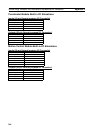
Address Bits Name Function