


82
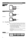
Wiring Servo Relay Units Section 3-4
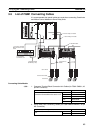
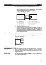
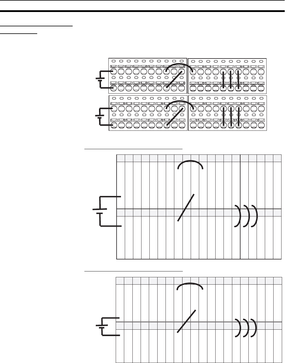
Example Servo Relay
Unit Wiring
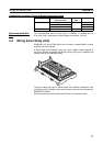
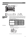
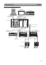
When Servo Relay Units for the FQM1 are used, the I/O power supply is pro-
vided from terminals 20-0, 21-1, and 60-40. The only additional wiring
required are the connections between the signals, as shown in the following
diagram.
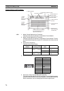
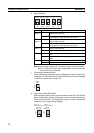
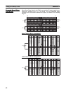
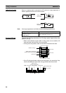
Upper Terminal Block Arrangement
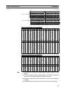
Lower Terminal Block Arrangement
60 79
0 1 2 3 4 5 6 7 8 9
0 1 2 3 4 5 6 7 8 9
0 1 2 3 4 5 6 7 8 9
0 1 2 3 4 5 6 7 8 9
0 1 2 3 4 5 6 7 8 9
0 1 2 3 4 5 6 7 8 9
0 1 2 3 4 5 6 7 8 9
0 1 2 3 4 5 6 7 8 9
019
5 V
24 V
Upper
terminal
block
Lower
terminal
block
60 61 62 63 64 65 66 67 68 69 70 71 72 73 74 75 76 77 78 79
5 V
IN4
IN5
IN6
IN7
TXD+
RXD+
40 41 42 43 44 45 46 47 48 49 50 51 52 53 54 55 56 57 58 59
0 V
OUT0
OUT1
OUT2
OUT3
TXD−
RXD−
---
5 V
Latch signal input 1
Latch signal input 2
CNT1 phase A LD + input
CNT1 phase B LD + input
Servo #1 phase Z LD + output
Voltage input (+)*
Servo #1 ALM
Servo #1 TGON
Servo #1 RUN
Servo #1 RESET
Servo #1 ECRST
Servo #1 MING
Latch signal 1 0 V
Latch signal 2 0 V
CNT1 phase A LD −/0 V
CNT1 phase B LD −/0 V
Servo #1 phase Z LD −/0 V
Voltage input (−)*
Servo #1 INP
Common (0 V)
Common (0 V)
Common (0 V)
Common (0 V)
Common (0 V)
---
20 21 22 23 24 25 26 27 28 29 30 31 32 33 34 35 36 37 38 39
24 V
24 V
IN0
IN1
IN2
IN3
IN8
IN9
IN10
IN11
FG
0 1 2 3 4 5 6 7 8 9 10 11 12 13 14 15 16 17 18 19
0 V
0 V
OUT4
OUT5
OUT6
OUT7
FG
---
---
---
---
---
---
24 V
Servo #2 ALM
Servo #2 TGON
Servo #2 RUN
Servo #2 RESET
Servo #2 ECRST
Servo #2 MING
Common (0 V)
Common (0 V)
Common (0 V)
Common (0 V)
Common (0 V)
Common (0 V)
Common (0 V)
Common (0 V)
Common (0 V)
Servo #2 INP