


344
System Setup, Auxiliary Area Allocations, and Built-in I/O Allocations Appendix C
Allocations That Are the Same for the Coordinator Module and Motion
Control Modules
System Flags
Program Error Flags
Other Error Flags and Bits
Error Log and Error Code
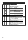
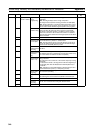
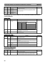
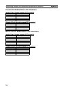
A524 00 to 15 Interrupt Counter 0
Counter PV
These words contain the interrupt counter PVs for interrupt input 0 to 3
operating in counter mode.
The counter PV starts decrementing from the counter SV. When the
counter PV reaches the 0, the PV is automatically reset to the SV.
Range: 0000 to FFFF
Module
A525 00 to 15 Interrupt Counter 1
Counter PV
A526 00 to 15 Interrupt Counter 2
Counter PV
A527 00 to 15 Interrupt Counter 3
Counter PV
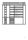
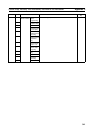
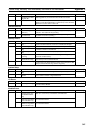
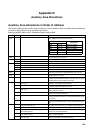
Address Bits Name Function Controlled by
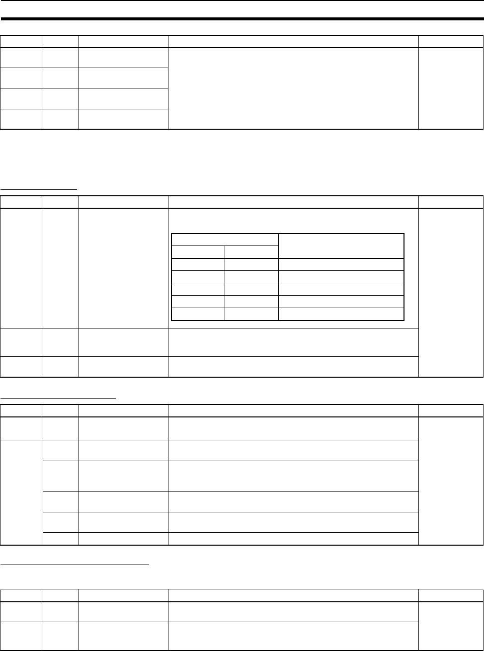
A000 to
A015
00 to 15 Subroutine Input Condi-
tion Flags
These flags contain the status of the input condition for JSB(982) when
JSB(982) is used to call a subroutine.
Module
A206 to
A207
00 to 15 Maximum Cycle Time These words store the maximum cycle time every cycle. The cycle
time is recorded in 8-digit hexadecimal
(unit: 0.01 ms).
A208 to
A209
00 to 15 Present Cycle Time These words store the present cycle time every cycle in 8-digit hexa-
decimal (unit: 0.01 ms).
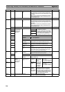
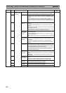
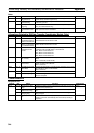
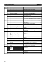
Address Bits Name Function Controlled by
A401 09 Program Error Flag
(fatal error)
ON when program contents are incorrect.
Module operation will stop.
Module
A405 11 No END Error Flag ON when there isn’t an END(001) instruction in each program within a
task.
12 Task Error Flag ON when a task error has occurred. The following conditions generate
a task error.
There isn’t a program allocated to the task.
13 Differentiation Overflow
Error Flag
The allowed value for Differentiation Flags which correspond to differ-
entiation instructions has been exceeded.
14 Illegal Instruction Error
Flag
ON when a program that cannot be executed has been stored.
15 UM Overflow Error Flag ON when the last address in UM (User Memory) has been exceeded.
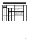
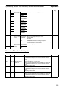
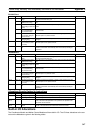
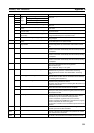
Address Bits Name Function Controlled by
A100 to
A199
00 to 15 Error Log Area When an error has occurred, the error code and error contents are
stored in the Error Log Area.
Module
A408 00 to 15 Error Log Pointer When an error occurs, the Error Log Pointer (binary) is incremented by
1 to indicate the location where the next error will be recorded as an
offset from the beginning of the Error Log Area (A100 to A199).
Address Bits Name Function Controlled by
Address Corresponding subroutines
Word Bits
A000 00 to 15 SBN000 to SBN015
A001 00 to 15 SBN016 to SBN031
A002 00 to 15 SBN032 to SBN047
to to to
A015 00 to 15 SBN240 to SBN255